

When using an active linearization loop some instability may occur depending upon the antenna VSWR. Therefore, careful selection of the feedback loop operational parameters is essential, which normally results in a slightly reduced linearization capability in favor of higher stability.
HELPFUL DIFFERENCES BETWEEN HF AND UHF
A broadband transceiver can cover a wide frequency range, which may span from HF up to UHF at 600 MHz or more. It is helpful to divide this frequency range into sub-bands. The differences between these sub-bands are, ideally, distinguished by different operational uses. These differences may enable opportunities to adapt key parameters of the transceiver architecture to perfectly match the operational requirements and facilitate transceiver architecture simplifications as well.
For example, the operational use of the HF Band normally requires a significantly higher output power than typically required for operation within the UHF Band (e.g., between 225 and 400 MHz). The split into sub-bands opens some room for optimization and simplification of the transceiver architecture while important key parameters can always be kept optimum. Such a split helps not only with the selection of the best, most suitable, components, but it also reduces the relative bandwidth required for key components like couplers, combiners and matching networks.
On the transmitter side, the design of an ultra-wideband amplifier may combine an HF amplifier using e.g., high-power HF/VHF transistors with a UHF amplifier using UHF/SHF transistors. Additionally, within the HF Band, antenna tuning units are often required to enable the use of a variety of antennas. These antenna tuning units must be included in the design of a transceiver because their selectivity provides help with respect to transmitter spectrum shaping as well as receiver robustness.
On the receive side, an HF receiver (independent of whether it employs direct sampling or IF sampling) may be used as an IF receiver after VHF/UHF down-conversion as part of an overall superheterodyne concept.
The split into sub-bands makes sense for components close to the antenna but is probably not required for other building blocks (e.g., signal generation). For an RF generator, it is possible today to create highly linear signals with low phase noise up-conversion to very high frequencies, and a split into sub-bands will not provide any advantage.
SHARING RESOURCES BETWEEN TX AND RX PATHS
In the co-site scenarios, as previously described, two identical transceivers were used to find the best operating point with respect to antenna decoupling, transmitter noise and interferer level at the receiver input. With a very low-noise transmit signal, antenna decoupling to a receiver can be quite low and the receiver will still not see any relevant desensitization due to transmitter noise, although the resulting interferer level may be very high.
A very low-noise transmitter may not be allowed to come close to a receiver front-end with a low robustness or a noisy transmit amplifier may not be allowed to come close to a very robust receiver without losing receiver performance.
The combination of minimum antenna decoupling, maximum allowed interferer level at the receiver input and required transmitter noise can be optimized. This will lead to the best overall system performance. A goal for the designer of a transceiver RF path is for the robustness of the receiver to match the noise performance of the transmitted signal with a given antenna decoupling. It will lead to equal contributions based on transmitter noise and those based on receiver effects if the antenna decoupling is decreased and reaches a minimum allowed operational limit.
As a result of perfect harmonization, the co-site filters within the transmit RF path are operated at the same power level as the pre-selector filters in the receiver RF path during the presence of strong interferers. With harmonized characteristics of the filters, it is possible to use them not only within the transmit path but also within the receive path by inserting an RF switch to employ the filters either as pre-selectors in the receive mode or as noise reduction filters in the transmit path (see Figure 15).
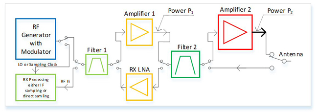
Figure 15 Resources shared between RX and TX.
The RF generator block is also shared. It delivers a high-quality low-noise noise-modulated signal for the transmit chain, and in the receive mode, it provides a local oscillator or clock signal to the receiver, either a superheterodyne concept or direct sampling.
CONCLUSION
A transceiver architecture comprises circuits for transmit and receive that can be designed to be completely independent from each other. An important step in optimization is to harmonize key parameters of the TX path with those of the RX path for best system performance with respect to co-location with low TX/RX antenna decoupling.
Harmonization of the RX path with the TX path within the transceiver architecture is then the basis for sharing valuable resources between these two parts. These shared resources may be high-quality filters that act as pre-selectors for the RX path or as co-site filters to reduce the noise of the TX path. Another sharable resource is the low-noise signal generator providing a clean transmit signal in the transmit mode which is also used as clean sampling, or mixing signal, in the receive mode for best desensitization performance. These steps can be the enablers for a compact and cost-effective design of a modern transceiver to provide excellent operational performance.
In the end, unit costs significantly influence the final architecture of a radio communication system and its components. For high-end installations (see Figure 16), such as military communication sites, radios can be adapted to the co-site situation. These radios can be equipped with special co-site options like hopping filters that are not only operated as pre-selectors for enhanced receiver robustness but are also reused as bandpass filters within the transmit chain as already shown in Figure 15.

Figure 16 High-end configurable V/UHF software-defined radio (SDR).
The co-site filters are active in all operational modes including fast frequency hopping. These special communication modes with hopping rates beyond 1,000 hops per second ensure a highly robust communication link even in the presence of intentional jamming signals. Superb RF specifications enable operation in complex antenna systems with antenna decoupling values as low as 25 dB (see Figure 17).
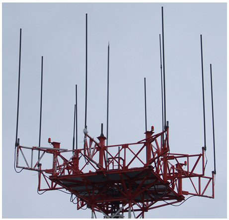
Figure 17 Complex antenna system with low decoupling.
For operation in such systems, the transmitters can be equipped with optional circulators to reduce transmitter backward intermodulation effects (see Figure 4) and, in combination with proper frequency planning as previously described, spurious free operation can be achieved.
TERMS AND DEFINITIONS
Cross-Modulation
Cross-modulation is an effect in which AM from a strong undesired signal is transferred to a weaker desired signal. Testing is usually done (in HF receivers) with a 20 kHz spacing between the desired and undesired signals, a 3 kHz IF bandwidth on the receiver, and the desired signal set to 1,000 μV EMF (-53 dBm). The undesired signal (20 kHz away) is amplitude-modulated to the 30 percent level. This undesired AM signal is increased in strength until an unwanted AM output 20 dB below the desired signal is produced.
A cross-modulation specification > 100 dB would be considered decent performance. This figure is often not given for modern HF receivers, but if the receiver has a good third-order intercept point, it is likely to also have good cross-modulation performance.
Cross-modulation is also said to occur naturally, especially in transpolar and North Atlantic radio paths where the effects of the aurora are strong. According to one (possibly apocryphal) legend, there was something called the “Radio Luxembourg Effect” discovered in the 1930s. Modulation from a very strong broadcaster (BBC) appeared on the Radio Luxembourg signal received in North America. This effect was said to be an ionospheric cross-modulation phenomenon. apparently occurring when the strong station is within 175 miles of the great circle path between the desired station and the receiver site.3, 4
Adjacent Channel Power Ratio
ACPR is an important performance metric used to characterize spectral regrowth in a transmitter front-end component or the entire chain. One of the main sources of spectral regrowth is PA nonlinearity. Therefore, this metric is often used to quantify the nonlinearity of a PA. It is also called adjacent channel leakage ratio (ACLR).
Inter-Symbol Interference
ISI is an effect where some energy of a modulation symbol also appears in other symbols and leads to interference. In the time domain it, looks like the symbols appear longer and are still present after the normal symbol time interval. This can be caused by propagation effects in the radio channel, but it may also be caused by nonlinear mechanisms within a transmitter’s PA. A receiver faced with ISI may not be able to clearly identify each symbol, which then leads to bit errors.
ACKNOWLEDGMENT
The authors would like to thank Manfred Fleischmann (Rohde & Schwarz), Robert Traeger (Rohde & Schwarz) and Harald Wickenhäuser (DK1OP, Rohde & Schwarz) for their support in the creation of this article.
References
- U. L. Rohde and T. Boegl, “The Perfect HF Receiver. What would it look Like Today?” Microwave Journal, Vol. 65, No. 5, May 2022, pp. 68-82.
- H. L. Hartnagel, R. Quay, U. L. Rohde and M. Rudolph, Fundamentals of RF and Microwave Techniques and Technologies, Chapter 9.6, Springer, 2023.
- J. Carr, The Technician´s EMI Handbook, Clues and Solutions, 1st Edition, Newnes, 2000.
- J. C. Pedro and N. B. Carvalho, Intermodulation Distortion in Microwave and Wireless Circuits, Artech House, 2003
For Further Reading
- U. L. Rohde, J. C. Whitaker and H. Zahnd, Communications Receivers: Principles and Design, McGraw Hill, Fourth Edition, 2017.
- ARRL. Web. https://www.arrl.org/.
- A. Farson (VA7OJ/AB4OJ), “A new Look at SDR Testing,” presented at the SDR Academy, 2016, Friedrichshafen, Germany.
- M. Fleischmann, A Novel Technique to Improve the Spurious-Free Dynamic Range of Digital Spectrum Monitoring Receivers, Dissertation, Brandenburgische Technische Universität Cottbus-Senftenberg, 2022.
- T. Boegl, “Test and Measurement for Radio Communication Equipment,” Rohde & Schwarz 2019.
- U. L. Rohde and M. Rudolph, RF/Microwave Circuit Design for Wireless Applications, Wiley, Second Edition, 2012.
- U. L. Rohde, Theory of Intermodulation and Reciprocal Mixing, Practice, Definitions and Measurements in Devices and Systems, Part 1, Synergy Microwave Corporation, 2001.
- P. Denisowski (KO4LZ), The Rebirth of HF, White Paper, Rohde & Schwarz North America. Web. https://www.rohde-schwarz.com/us/knowledge-center/videos/webinar-the-rebirth-of-hf-video-detailpage_251220-908608.html.