
TWO-PORT TECHNIQUES
A popular classical approach for two-port analysis, where two fixture arms are extracted simultaneously, is sometimes termed adapter removal (see Martens6 and the references therein); although this term is sometimes used specifically for the case where a single fixture is moved from being attached to one instrument port to being attached to the other instrument port. This discussion generalizes to two fixture arms. While the concept has several different implementations, one is essentially a doubling of the BP analysis with the thru information not actually used. Other implementations use the thru data to augment the fixture transmission terms, often in a least-squared sense that is reflected in this article; the method is illustrated in Figure 7. Since a calibration is being performed at the inner reference plane, why is extraction needed? This is sometimes done so the fixture parameters can be recalled in conjunction with a simpler instrument calibration for future measurements, when the DUT plane calibration may not be practical.
A simple partial information technique does a gross match assignment by using only the instrument side reflection data and, assuming the inner interface is perfect, assigns the measured mismatch to S11 and S22 of the fixture arm, either with symmetry or, usually, all mismatch assigned to one side or the other of the fixture. Symmetry is assumed in this analysis. The insertion loss is simply the square root of the measured insertion loss of both fixture arms together. In dB, it is a halving of the measured loss; hence, this method is sometimes termed “divide by 2.” Because of the match handling coarseness, this approach is best suited to a well-matched fixture12 and is labeled D1 in the following measurements. A more recent partial information scheme also goes under the “phase localized” label used in the one-port section, but here the correlation with phase kernels is applied to transmission as well as reflection data, and fixture insertion loss is derived from processing on the measured transmission data.14 This process is illustrated in Figure 8, with the results labeled PLD in the following measurements. A calibration exists at the instrument reference planes - short, short, load, thru (SSLT) in this case - and transmission and reflection data through the fixture pair are correlated against a range of phase kernels.
TWO-PORT MEASUREMENTS
The two fixture setup is measured using all three methods, and both fixture arms have similar parameters. |S21| is plotted in Figure 9a, and all methods agree within about 0.1 dB except above 215 GHz. The D1 method shows higher spatial frequency ripple, which appears to arise from the misallocation of mismatch centers. Separation by phase localization is cleaner with PLD, and the bandwidth enables this separation since the dominant centers are separated by about 250 ps. The adapter removal method misses some structures, and adds one of its own, presumably because of repeatability issues on the many connections. On repeated extractions, the 2σ repeatability for the adapter removal approach is ±0.2 dB, while those for D1 and PLD are both under ±0.1 dB. All methods identify the resonant structure at about 172 GHz, caused by a support structure near the DUT plane.
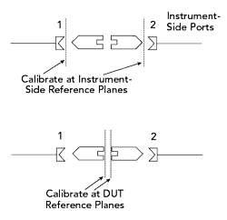
Figure 7 Adapter removal method two-port extraction.
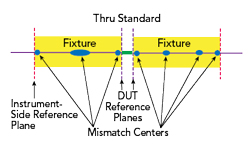
Figure 8 Transmission based, phase localized, two-port extraction.
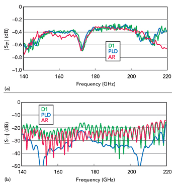
Figure 9 Extracted fixture |S21| (a) and |S11| (b) comparing the D1, PLD and AR two-port methods.
The extracted |S11| on the instrument side is plotted in Figure 9b for the three methods, with a bit more variance here, although return loss levels are relatively high. Based on simulation, the D1 method appears to underestimate return loss, but the allocation is forcibly symmetric, so it is not surprising there are some variances. The adapter removal method shows higher reflections at some frequencies, likely due to heightened sensitivity to the characterization of the standards used at the DUT plane.
CONCLUSION
In repeatability-challenged fixtures used at higher mmWave frequencies, classical extraction approaches for de-embedding may have suboptimal performance due to repeatability or the ability to fabricate and characterize standards to use at the DUT plane. Partial information methods that place less stress on those standards and more stress on fixture assumptions have evolved over the years and can produce improved results if the assumptions are met. Some of the more recent algorithms that make assumptions about locations of mismatches in some mmWave fixtures may yield better results than measurements that ignore mismatches or assume symmetry.
References
- R. Bauer and P. Penfield, “De-Embedding and Unterminating,” IEEE Transactions on Microwave Theory and Techniques, Vol. 22, No. 3, March 1974, pp. 282–288.
- H. Xu and E. Kasper, “A De-Embedding Procedure for One-Port Active mm-Wave Devices,” Topical Meeting on SiRF, January 2010, pp. 37–40.
- J. Wang, R. Groves, B. Jagannathan and L. Wagner, “Experimental Analysis of On-Wafer De-Embedding Techniques for RF Modeling of Advanced RFCMOS and BiCMOS Technologies,” 69th ARFTG Conference Digest, June 2007.
- X. Wei, G, Niu, S. L. Sweeney and S. S. Taylor, “Singular-Value-Decomposition Based Four Port De-Embedding and Single-Step Error Calibration for On-Chip Measurement,” Proceedings of the IEEE MTTS International Microwave Symposium, June 2007, pp. 1497–1500.
- S. Moon, X. Ye and R. Smith, “Comparison of TRL Calibration vs. 2x Thru De-Embedding Methods,” IEEE Symposium on Electromagnetic Compatibility and Signal Integrity, March 2015.
- J. Martens, “Common Adapter/Fixture Extraction Techniques: Sensitivities to Calibration Anomalies,” 74th ARFTG Conference, December 2009.
- D. F. Williams, ”500 GHz–750 GHz Rectangular-Waveguide Vector-Network-Analyzer Calibrations,” IEEE Transactions on THz Science Technology, Vol. 1, No. 2, February 2011, pp. 364–377.
- D. F. Williams, C. M. Wang and U. Arz, “An Optimal Multiline TRL Calibration Algorithm,” IEEE MTT International Microwave Symposium Digest, June 2003, pp. 1819–1822.
- H. Li, A. R. Kerr, J. L. Hesler and R. M. Weikle, “Repeatability of Waveguide Flanges with Worst-Case Tolerances in the 500–750 GHz Band,” 79th ARFTG Conference, June 2012.
- M. Horibe and R. Kishikawa, “Investigations of Connection Repeatability for Waveguides with Different Size Apertures,” 82nd ARFTG Microwave Measurement Conference, June 2013.
- Y. S. Lau and D. Vondran, “An Innovative Waveguide Interface and Quarter-Wavelength Shim for the 220-325 GHz Band,” 80th ARFTG Microwave Measurement Conference, December 2012.
- G. F. Engen, “An Evaluation of the ‘Back-to-Back’ Method of Measuring Adaptor Efficiency,” IEEE Transactions on Instrumentation and Measurement, Vol. 19, No. 1, February 1970, pp. 18–22.
- H. Barnes and A. Ciccomancini, “Performance at the DUT: Techniques for Evaluating Performance of an ATE System at the Device Under Test Socket,” DesignCon, February 2008.
- J. Martens, “Simplified De-embedding Techniques: Some Effects of Match and Geometry Assumptions,” DesignCon, January 2015.
- E. Mayevskiy, “A New Test Fixture Crosstalk De-Embedding Technique Using Time-Domain Gating,” DesignCon, February 2008.
- J. Martens, “MM-Wave Partial Information De-Embedding: Errors and Sensitivities,” ARFTG Microwave Measurement Conference, June 2018.