 Rectangular and Taper Chambers, Compact Ranges, Near Field Ranges.
Reply to this Article
Read all responses
Win: The first five contributors are eligible to receive a complimentary copy of the textbook Electrical Engineering – A Pocket Reference from Artech House.
There are a large number of different approaches to measure antennas. Here’s a brief introduction and guide as to which approach may be better for the different antennas type to be measured.
Introduction
Not that long ago, Antenna measurement chambers were systems rarely found outside of defense contractors, military and the aerospace industry and some academic institutions.
With the advent of what can be called the wireless revolution the need for antennas spread into the realm of non-defense related enterprises. The need for antennas has grown and while a lot of them may be electrically small affairs with the typical short dipole pattern, the fact is that these antennas are mounted onto electrically larger devices such as routers, laptops, and automobiles.
The larger structure influences the pattern and the engineer can no longer assume the performance of the antenna. It must be measured or modeled. But what is the best approach to measure these antennas? And what does it mean to measure the radiation pattern?
Antenna Patterns Antenna Ranges
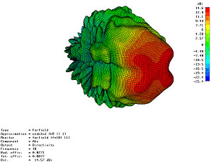
Most antenna textbooks will define the radiation pattern or radiation diagram as a 3D map of the radiated power density of an antenna for different directions as is shown in the plot seen in Figure 1.

Figure 1. a radiation pattern.
So what we are doing is to “walk” around the antenna while measuring the field it radiates. Since most engineers are lazy (only an extremely lazy person will go through the effort of studying obscure physics laws in order to design a machine that will perform certain task for him). Rather than “walk” around the antenna it is better to rotate the antenna while we comfortably “sit” at a given position measuring the radiated field. Hence to measure the pattern we need an open area or anechoic area where we will rotate the antenna under test while we measure its radiation from a secondary antenna.
As humans we like to classify everything in order to study it. Following this tradition of “classification for study” I will now proceed to classify the main antenna chambers into groups.
I first divide the family of anechoic antenna ranges into direct illumination and other approaches. In direct illumination there is a far field direct path between the antenna under test and the measuring antenna. Under this category fall the typical rectangular chambers and taper chambers.
The others are approaches that fail to meet the requirements of the direct illumination. Either the far field requirement is not there (because we are in the near field as in near field scanning systems) or because a reflective surface is used to direct the radiation between the antenna under test and the measuring antenna so there is no longer a direct illumination between the antennas. Based on this division here is the antenna range classification with its primary examples:
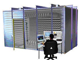
• Rectangular Anechoic Direct Illumination. Place the source antenna and the AUT on the far field of each other and rotate the AUT while measuring the radiation with the source antenna. The walls of the chamber are all treated with anechoic material and the goal is to minimize reflections.
• Taper Anechoic: Place the source antenna and the AUT on the far field of each other and rotate the AUT while measuring the radiation with the source antenna. The walls are all treated with absorber but unlike the rectangular chamber the geometry of the taper is used not to minimize the reflections but to create a smoother illumination at low frequencies.
• Compact Range. A shaped reflector is used to create a plane wave similar to the far field so that the antenna under test can be measured at range lengths shorter that its far field.
• Near Field Range. Instead of measuring the far field the near field is measured and mathematically using the induction and physical equivalent principles of electromagnetics the far field is computed

Figure 2. A rectangular anechoic chamber.

Figure 3. A taper anechoic chamber.

Figure 4. A compact range (courtesy of MI technologies).

Figure 5. A near field scanning system (courtesy of MI technologies).
Far Field Requirement
Let's now take a break and review the idea of far field, as this is going to help in determining the type of range more suitable for different antennas. In measuring radiation pattern of antennas the far field performance is what the antenna engineer is interested in measuring. Theoretically, the far field is obtained by obtaining the radiated field and then taking the limit as the distance from the antenna goes to infinity.
Physically speaking infinity is a large enough distance. Finding what is an acceptable approximation to the far field is an important notion in antenna engineering. In the far field the waves are theoretically plane waves. However as we get closer to the source the waves cease to look plane and they become more spherical in nature.
Figure 6 shows that there is a small length difference δ between the rays incident on the area of size Dmax. This distance difference translates in to a phase difference in the field along Dmax.

Figure 6. Phase deviation between the spherical waves and the plane wave.
Hence what figure 6 shows is the difference between the spherical waves and the plane waves that exist in the far field. If the phase difference is smaller than π/8 radians then it can be said that we are in the far field.
Let us derive the far field condition. By the Pythagorean theorem:

So δ can be written in terms of the other parameters as

Using binomial expansion to reduce the above equation we arrive to the following term

Since we know that the far field condition is met when the phase difference across Dmax is π/8 then using the propagation constant

the phase difference is given by

The above equation can be solved for R giving the well known far field condition [1]

What we need out of this mathematical discussion is that the largest that an antenna is in terms of wavelengths the furthest the far field region is located.
Which Range for Which Antenna
Based on this knowledge of the far field my rule of thumb is that direct illuminations chambers are suitable for antennas up to 10 wavelengths in size. Beyond that the chamber becomes too large for a direct illumination measurements and it makes economic sense to go for a more complex and expensive compact range or near field range.
Frequency is also a factor, because after all, wavelengths depend on frequency and the lower the frequency the longer the wavelength. For antennas that meet the wavelength requirement for direct illumination the break between using a taper chamber or a rectangular chamber is at about 500 to 600MHz.
For Electrically large antennas, the choice between a near field range and a compact range can be also related to the frequency, compact ranges for frequencies bellow 2GHz become extremely large physically and the chamber to house them also become very large.
In conclusion, I hope that this gave you a brief introduction into different antenna ranges and which may the best solution for your measurement needs. Any questions or comments?
References
1. Balanis C. A. Antenna Theory: Analysis and design, 2d Ed, Wiley: New York, NY, 1997.
