
SIMULATION AND MEASUREMENT
The fabricated prototype of the patch antenna is shown in Figure 5, and Figure 6 shows the measurement set-up for reflection measurements. Figure 7 compares the simulated and measured reflection coefficients for LC E7 mixtures with two permittivities. Both the simulated and measured results show an adjustable frequency from 5.64 GHz with no magnetic field applied (H = 0 Oe, εr⊥ = 2.72 and tan(δ) = 0.12) to 5.44 GHz with the two magnets positioned 5 mm from each side of the antenna (H = 1200 Oe, εr∥ = 3.17 and tan (δ) = 0.02). The difference in resonant frequencies is ∆Fr = 200 MHz, representing a 3.6 percent tunable range. The minimum simulated value of |S11| at 5.64 GHz is -26 dB improving when the 1200 Oe magnetic field is applied, which is linked to the decrease in tan(δ) from 0.12 to 0.02.
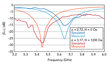
Figure 7 Simulated vs. measured |S11| with two LC E7 mixture permittivities.
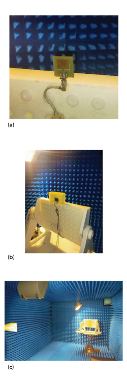
Figure 8 Radiation pattern test set-up: antenna on a mount without magnets (a), antenna with magnets (b) and view of anechoic chamber (c).
Figure 8 shows the test set-up for measuring the antenna patterns, both peak gain (see Figure 9) and the E-plane patterns (see Figure 10). The figures compare the simulated and measured results. The measured peak gains for the two cases are approximately 0.5 dB lower than the simulated values. The maximum gain of the patch antenna loaded with LC E7 is approximately 4.05 dB, with a radiation efficiency of 61 percent. The measured gain patterns are similar to the simulations, with the measured patterns more omnidirectional than predicted. The difference between measured and simulated is less in the case of no applied magnetic field, i.e., 5.64 GHz resonance (see Figure10a). At 5.4 GHz, with the antenna magnetically biased, the magnets disturb the gain pattern measurement (see Figure 10b). Not surprisingly, the metallic masses mounted to the sides and close to the aperture affect the pattern, scattering the radiation to the rear. To minimize this, an alternative method to create the magnetic field using Helmholtz coils15 would likely minimize this effect.
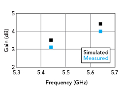
Figure 9 Simulated vs. measured peak gain with two LC E7 mixture permittivities.
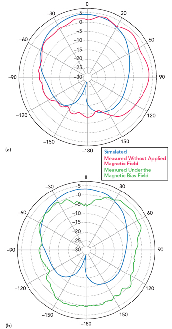
Figure 10 Simulated vs. measured E-plane patterns: without applied magnetic field at 5.64 GHz (a) and with a magnetic field at 5.44 GHz (b).
The response time of the LC is relatively long—on the scale of milliseconds—after the application of the externally applied magnetic field. This is less of a concern with the discovery of new types of LCs that exhibit short response times and low losses at microwave and mmWave frequencies.
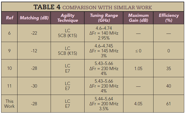
Table 4 compares the performance of this antenna with similar work. This design achieves a similar tuning range with higher gain and efficiency.
CONCLUSION
A microstrip patch antenna was fabricated with an LC E7 dielectric layer using a new method for adjusting the resonant frequency: magnets spaced 5 mm on either side of the antenna, applying a magnetic field of 1200 Oe. The magnetic field changes the LC permittivity, shifting the antenna’s resonant frequency from 5.64 to 5.44 GHz, which is suitable for Wi-Fi applications. The measured radiation patterns are stable over the tuning range. In addition to the performance, the LC reconfigurable antenna has a low profile and is low cost to manufacture.
References
- A. -F. Sheta and S. F. Mahmoud, “A Widely Tunable Compact Patch Antenna,” IEEE Antennas and Wireless Propagation Letters, Vol. 7, March 2008, pp. 40–42.
- F. Sboui, J. Machac and A. Gharsallah, “Tunable Slot Antenna Backed by Substrate Integrated Waveguide Cavity,” International Journal of RF and Microwave Computer-Aided Engineering, Vol. 28, No. 9, October 2018.
- F. Sboui, J. Machac and A. Gharsallah, “Low-Profile Slotted SIW Cavity Backed Antenna for Frequency Agility,” Radioengineering, Vol. 28, No. 2, June 2019, pp. 386–390.
- K. Topalli, E. Erdil, O. A. Civi, S. Demir, S. Koc and T. Akin, “Tunable Dual Frequency RF MEMS Rectangular Slot Ring Antenna,” Sensors and Actuators A: Physical, Vol. 156, No. 2, December 2009, p. 373–380.
- M. Sazegar, Y. L. Zheng, H. Maune, C. Damm, X. H. Zhou, J. Binder and R. Jakoby, “Low-Cost Phased-Array Antenna Using Compact Tunable Phase Shifters Based on Ferroelectric Ceramics,” IEEE Transactions on Microwave Theory and Techniques, Vol. 59, No. 5, May 2001, pp. 1265–1273.
- N. Martin, P. Laurent, C. Person, P. Gelin, and F. Huret, “Patch Antenna Adjustable in Frequency using Liquid Crystal,” 33rd European Microwave Conference, October 2003, Vol. 3, pp. 1417–1420. DOI: 10.1109/EUMC.2003.177573.
- N. Martin, P. Laurent, C. Person, P. Gelin and F. Huret, “Size Reduction of a Liquid Crystal-Based, Frequency-Adjustable Patch Antenna,” Proceedings of the 34th European Microwave Conference, Vol. 2, November 2004, pp. 825–828.
- F. Sboui, J. Machac, L. Latrach and A. Gharsallah, “Triple Band Tunable SIW Cavity Antenna with Cristal Liquid Materials for Wireless Applications,” IEEE 19th Mediterranean Microwave Symposium, October 2019.
- N. C. Papanicolaou, M. A. Christou and A. C. Polycarpou, “Frequency-Agile Microstrip Patch Antenna on a Biased Liquid Crystal Substrate,” Electronics Letters, Vol 51, No. 3, February 2015, pp. 202–204.
- A. C. Polycarpou, M. A. Christou and N. C. Papanicolaou, “Tunable Patch Antenna Printed on a Biased Nematic Liquid Crystal Cell,” IEEE Transactions on Antennas and Propagation, Vol. 62, No. 10, July 2014, pp. 4980–4987.
- L. Liu and R. J. Langley, “Liquid Crystal Tunable Microstrip Patch Antenna,” Electronics Letters, Vol. 44, No. 20, October 2008, pp. 1179–1180.
- S. Missaoui, S. Missaoui and M. Kaddour, “Tunable Microstrip Patch Antenna Based on Liquid Crystals,” XXIst International Seminar/Workshop on Direct and Inverse Problems of Electromagnetic and Acoustic Wave Theory, September 2016.
- L. -C. Huang, C. -M. Fu, C. -W. Lee and A. -C. Sun, “Magnetic Field Effects on the Electric Modulus Properties of Nematic Mixture E7,” Current Applied Physics, Vol. 14, No. 1, January 2014.
- C. A. Balanis, Antenna Theory: Analysis and Design, Third Edition, Wiley, 2005.
- G. Podaru, J. Moore, R. K. Dani, P. Prakash and V. Chikan, “Nested Helmholtz Coil Design for Producing Homogeneous Transient Rotating Magnetic Fields,” Review of Scientific Instruments, Vol. 86, No. 3, March 2015.