
Magnetically Tunable U-Slot Microstrip Patch Antenna Based on Nematic Liquid Crystal Materials
A reconfigurable U-slot microstrip patch antenna uses a nematic state liquid crystal (LC) mixture operating at 5 GHz for wireless communications such as Wi-Fi. An external magnetic field from 0 to 1200 Oersted changes the relative permittivity of the LC to adjust the patch resonant frequency. A tuning range of 200 MHz in both measurement and simulation is demonstrated with a maximum gain of 4.05 dB. LC is considered a good candidate for reconfigurable antennas due to its low cost, low profile and performance.
Wireless communication has evolved to become a necessary aspect of our daily lives. At the same time, the growth of the market has led to an increase in the number of standards allocated to systems and terminals operating on different frequency bands. This multiplicity of communication standards typically requires the use of several antennas, each dedicated to a specific band. This, however, implies an increase in the physical size of the system with a significant impact on its cost, energy consumption and complexity. Alternatively, the use of a reconfigurable antenna operating over several frequency bands enables reduced size, power consumption and cost.
A patch antenna has many advantages, such as low weight, moderate cost and ease of manufacture. Nevertheless, for some applications, its bandwidth is too narrow. This limitation can be overcome by making it reconfigurable using lumped elements such as PIN diodes,1 varactor diodes,2,3 RF MEMS switches4 or tunable materials such as ferroelectrics5 and LC.6-13 The possibility of changing the LC dielectric constant in its nematic state through an applied electric or magnetic field has attracted researchers in the microwave community for some decades.
In this work, a patch antenna is designed, using the characteristics of LCs to add reconfigurability. The nematic state LC mixture E7 is injected between the patch antenna and ground. Simulation and measurements demonstrate a tunable range of 200 MHz, with the application of a magnetic field, and a peak gain of 4.05 dB.
PROPERTIES OF LCs
The nematic state of a LC is generally used in microwave and mmWave systems with the external application of an electric or magnetic field to change its dielectric constant. The use of an electric field to change the orientation of LC molecules is, by analogy, equivalent to the use of a magnetic field. In this work, a magnetic field is used to shift the frequency of a patch antenna. To switch on the magnetic field, two magnets are spaced 5 mm on either side; to switch off the magnetic field, the two magnets are removed.
The magnetic field applied to the LC must be greater than 600 Oe.13 To ensure that the molecules of the LC are parallel to the applied magnetic field, the two magnets are positioned 5 mm from both sides of the antenna, where the total magnetic field strength equals 1200 Oe (see Figure 1). The LC molecules are oriented according to the magnetic field applied. When no magnetic field is applied, alignment of the molecules is promoted by covering the lower and upper contact surfaces of the LC layer with a microscopic polyamide film. This achieves the perpendicular permittivity εr⊥. When the applied magnetic field is equal to 1200 Oe, the molecules are oriented in the same direction as the magnetic field, which achieves parallel permittivity εr∥. Martin et al.7 used a foam substrate loaded with LC K15 to obtain a tunable frequency range of 140 MHz from 4.6 to 4.74 GHz and a tuning range of 4 percent, from 5.43 to 5.66 GHz, was achieved using LC E7.13

Figure 1 Parallel and perpendicular permittivity (a). Effective permittivity and loss tangent vs. applied bias magnetic field (b).13
PATCH ANTENNA DESIGN

Figure 2 Microstrip patch antenna without LC (a) and simulated |S11| (b).
A 5 GHz antenna (see Figure 2a) was designed using Equations 1 through 5.14 The substrate was FR-4, with a relative permittivity εr = 4.4 and a thickness h = 1.6 mm. The patch dimensions were Ls = 30 and Ws = 30 mm. The inset feed Li and gap Wg = 5.7 and 0.2 mm, respectively. A 50 Ω microstrip line (Lf = 2.9 mm; Wf = 12.05 mm) was used to feed the patch on a grounded substrate. Design choices were based on simulations using the CST Studio Suite software. The width, W, was calculated using
where fc is the center frequency and εreff is the effective permittivity.
εreff is given by

where h is the thickness of the dielectric substrate.
∆L, the extended incremental length of the patch, is calculated from

The effective length is determined by

The actual length of the patch is determined by

The final dimensions of the design are listed in Table 1.
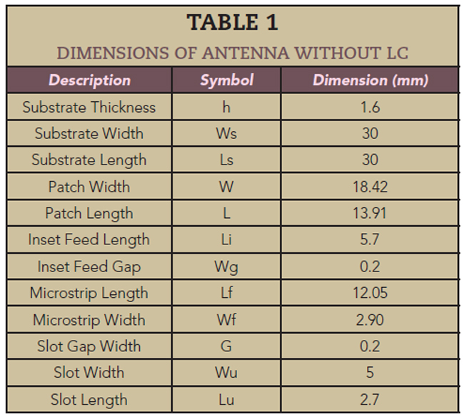
Figure 2b shows the simulated reflection coefficient, where |S11| reaches a value less than -19 dB at the resonant frequency of 5.07 GHz. The simulated radiation patterns without the LC (see Figure 3) show a maximum gain of 2.28 dB and a directivity of 6.80 dBi at 5.07 GHz.
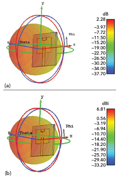
Figure 3 Simulated 3D gain (a) and directivity (b) at the 5.07 GHz resonant frequency.
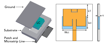
Figure 4 Microstrip patch antenna loaded with LC E7.
The LC E7 mixture in its nematic state, i.e., as a liquid material, is injected into a cavity created above the ground with a depth of 1.5 mm on the substrate, and the upper and lower contact surfaces of the LC layer are covered by a microscopic polyamide film (see Figure 4). Following a parametric study to determine the best position for the cavity, the LC layer is placed under the patch. The dimensions of the LC layer are listed in Table 2 and its electrical characteristics are summarized in Table 3.


Figure 5 Fabricated prototype antenna.

Figure 6 Test set-up for the prototype antenna without (a) and with (b) an applied magnetic field.
SIMULATION AND MEASUREMENT
The fabricated prototype of the patch antenna is shown in Figure 5, and Figure 6 shows the measurement set-up for reflection measurements. Figure 7 compares the simulated and measured reflection coefficients for LC E7 mixtures with two permittivities. Both the simulated and measured results show an adjustable frequency from 5.64 GHz with no magnetic field applied (H = 0 Oe, εr⊥ = 2.72 and tan(δ) = 0.12) to 5.44 GHz with the two magnets positioned 5 mm from each side of the antenna (H = 1200 Oe, εr∥ = 3.17 and tan (δ) = 0.02). The difference in resonant frequencies is ∆Fr = 200 MHz, representing a 3.6 percent tunable range. The minimum simulated value of |S11| at 5.64 GHz is -26 dB improving when the 1200 Oe magnetic field is applied, which is linked to the decrease in tan(δ) from 0.12 to 0.02.
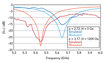
Figure 7 Simulated vs. measured |S11| with two LC E7 mixture permittivities.
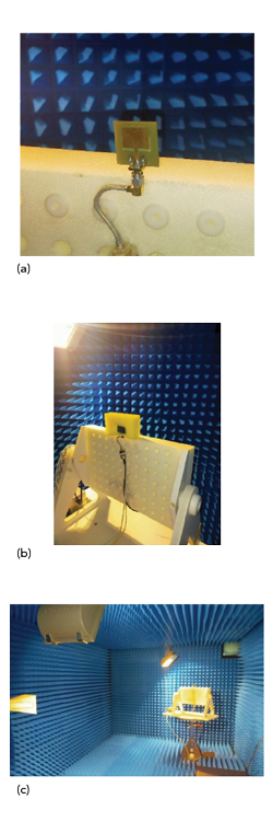
Figure 8 Radiation pattern test set-up: antenna on a mount without magnets (a), antenna with magnets (b) and view of anechoic chamber (c).
Figure 8 shows the test set-up for measuring the antenna patterns, both peak gain (see Figure 9) and the E-plane patterns (see Figure 10). The figures compare the simulated and measured results. The measured peak gains for the two cases are approximately 0.5 dB lower than the simulated values. The maximum gain of the patch antenna loaded with LC E7 is approximately 4.05 dB, with a radiation efficiency of 61 percent. The measured gain patterns are similar to the simulations, with the measured patterns more omnidirectional than predicted. The difference between measured and simulated is less in the case of no applied magnetic field, i.e., 5.64 GHz resonance (see Figure10a). At 5.4 GHz, with the antenna magnetically biased, the magnets disturb the gain pattern measurement (see Figure 10b). Not surprisingly, the metallic masses mounted to the sides and close to the aperture affect the pattern, scattering the radiation to the rear. To minimize this, an alternative method to create the magnetic field using Helmholtz coils15 would likely minimize this effect.
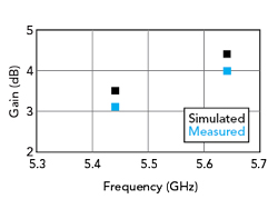
Figure 9 Simulated vs. measured peak gain with two LC E7 mixture permittivities.
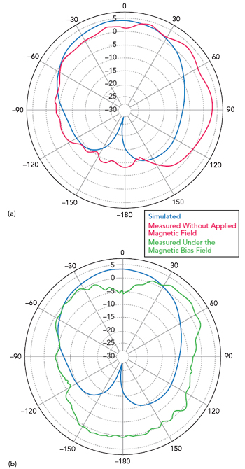
Figure 10 Simulated vs. measured E-plane patterns: without applied magnetic field at 5.64 GHz (a) and with a magnetic field at 5.44 GHz (b).
The response time of the LC is relatively long—on the scale of milliseconds—after the application of the externally applied magnetic field. This is less of a concern with the discovery of new types of LCs that exhibit short response times and low losses at microwave and mmWave frequencies.
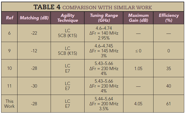
Table 4 compares the performance of this antenna with similar work. This design achieves a similar tuning range with higher gain and efficiency.
CONCLUSION
A microstrip patch antenna was fabricated with an LC E7 dielectric layer using a new method for adjusting the resonant frequency: magnets spaced 5 mm on either side of the antenna, applying a magnetic field of 1200 Oe. The magnetic field changes the LC permittivity, shifting the antenna’s resonant frequency from 5.64 to 5.44 GHz, which is suitable for Wi-Fi applications. The measured radiation patterns are stable over the tuning range. In addition to the performance, the LC reconfigurable antenna has a low profile and is low cost to manufacture.
References
- A. -F. Sheta and S. F. Mahmoud, “A Widely Tunable Compact Patch Antenna,” IEEE Antennas and Wireless Propagation Letters, Vol. 7, March 2008, pp. 40–42.
- F. Sboui, J. Machac and A. Gharsallah, “Tunable Slot Antenna Backed by Substrate Integrated Waveguide Cavity,” International Journal of RF and Microwave Computer-Aided Engineering, Vol. 28, No. 9, October 2018.
- F. Sboui, J. Machac and A. Gharsallah, “Low-Profile Slotted SIW Cavity Backed Antenna for Frequency Agility,” Radioengineering, Vol. 28, No. 2, June 2019, pp. 386–390.
- K. Topalli, E. Erdil, O. A. Civi, S. Demir, S. Koc and T. Akin, “Tunable Dual Frequency RF MEMS Rectangular Slot Ring Antenna,” Sensors and Actuators A: Physical, Vol. 156, No. 2, December 2009, p. 373–380.
- M. Sazegar, Y. L. Zheng, H. Maune, C. Damm, X. H. Zhou, J. Binder and R. Jakoby, “Low-Cost Phased-Array Antenna Using Compact Tunable Phase Shifters Based on Ferroelectric Ceramics,” IEEE Transactions on Microwave Theory and Techniques, Vol. 59, No. 5, May 2001, pp. 1265–1273.
- N. Martin, P. Laurent, C. Person, P. Gelin, and F. Huret, “Patch Antenna Adjustable in Frequency using Liquid Crystal,” 33rd European Microwave Conference, October 2003, Vol. 3, pp. 1417–1420. DOI: 10.1109/EUMC.2003.177573.
- N. Martin, P. Laurent, C. Person, P. Gelin and F. Huret, “Size Reduction of a Liquid Crystal-Based, Frequency-Adjustable Patch Antenna,” Proceedings of the 34th European Microwave Conference, Vol. 2, November 2004, pp. 825–828.
- F. Sboui, J. Machac, L. Latrach and A. Gharsallah, “Triple Band Tunable SIW Cavity Antenna with Cristal Liquid Materials for Wireless Applications,” IEEE 19th Mediterranean Microwave Symposium, October 2019.
- N. C. Papanicolaou, M. A. Christou and A. C. Polycarpou, “Frequency-Agile Microstrip Patch Antenna on a Biased Liquid Crystal Substrate,” Electronics Letters, Vol 51, No. 3, February 2015, pp. 202–204.
- A. C. Polycarpou, M. A. Christou and N. C. Papanicolaou, “Tunable Patch Antenna Printed on a Biased Nematic Liquid Crystal Cell,” IEEE Transactions on Antennas and Propagation, Vol. 62, No. 10, July 2014, pp. 4980–4987.
- L. Liu and R. J. Langley, “Liquid Crystal Tunable Microstrip Patch Antenna,” Electronics Letters, Vol. 44, No. 20, October 2008, pp. 1179–1180.
- S. Missaoui, S. Missaoui and M. Kaddour, “Tunable Microstrip Patch Antenna Based on Liquid Crystals,” XXIst International Seminar/Workshop on Direct and Inverse Problems of Electromagnetic and Acoustic Wave Theory, September 2016.
- L. -C. Huang, C. -M. Fu, C. -W. Lee and A. -C. Sun, “Magnetic Field Effects on the Electric Modulus Properties of Nematic Mixture E7,” Current Applied Physics, Vol. 14, No. 1, January 2014.
- C. A. Balanis, Antenna Theory: Analysis and Design, Third Edition, Wiley, 2005.
- G. Podaru, J. Moore, R. K. Dani, P. Prakash and V. Chikan, “Nested Helmholtz Coil Design for Producing Homogeneous Transient Rotating Magnetic Fields,” Review of Scientific Instruments, Vol. 86, No. 3, March 2015.