In a previous part of this series on power integrity, we reviewed the meaning of Power Supply Ripple Rejection (PSRR) and in this and the following blogs, we continue to explore the subject. When choosing an LDO or linear regulator product, many examples can be seen of promotional material and/or datasheets highlighting ‘high PSRR’ performance, as if ‘PSRR’ is the only parameter to consider. This ‘high PSRR’ phrase has no meaningful value to add, like a used car salesman saying ‘it’s a great car’ where we all know this might just mean ‘this car is operational with no obvious problem’. This ‘high PSRR’ LDO claim is one of the worst habits in the power semiconductor industry, masking what performance is important when choosing a linear regulator.
Here, we are dealing with the subject of RF signal integrity to power integrity and we need to have a clear understanding of how PSRR performance benefits us and in what kind of application use cases. For sure, just inserting a ‘high PSRR’ LDO is not a magical tool to eliminate all power supply integrity concerns.
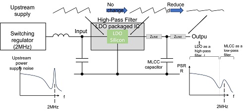
So, what is the correct interpretation of a given PSRR performance and its benefits? I would say that PSRR is a high-power and low-impedance active filter characteristic associated with a voltage regulator. As shown in Figure 1, we have a dirty input ‘upstream supply’, we insert an LDO regulator and we have our clean output power supply to the signal chain or RF load devices.

PSRR characterized as an active filter
Just like filters in the signal chain or RF world, each power filter has its performance characteristic and it can do a good job in its designed target frequency region. Conversely, any filter can bring you little benefit out of its target frequency range.
In this series, I will repeat this question many times: What is your target frequency of concern? When discussing power supply designs, many times I hear: ‘I need a high PSRR of (say) 80 dB’
My response is always:
‘What’s your frequency of concern? - is it 80 dB at 1 Hz, 80 dB at 10 MHz, or 80 dB at 1 GHz for example’?
In the 2nd part of this series, we stated that all Voltage Regulator Modules (VRMs), such as LDOs, are power amplifiers. By using a VRM internal error amplifier (EA), an active filter is formed, just like an operational amplifier (op amp) based filter, and this filter performance defines the PSRR. A VRM’s EA works in a simple negative feedback configuration, with nothing in the way of frequency modulation. So, power supply input noise, at 10 kHz for example, appears at the output at 10 kHz reduced by the PSRR ratio. When your frequency of concern is 100 kHz say, you check the VRM PSRR curve at 100 kHz for the attenuation value.
VRM PSRR is bandwidth limited! The example simulation below illustrates the control loop bandwidth limit of a VRM PSRR (see Figures 2 & 3). This simulation deck can be downloaded from the Qorvo repository on GitHub.
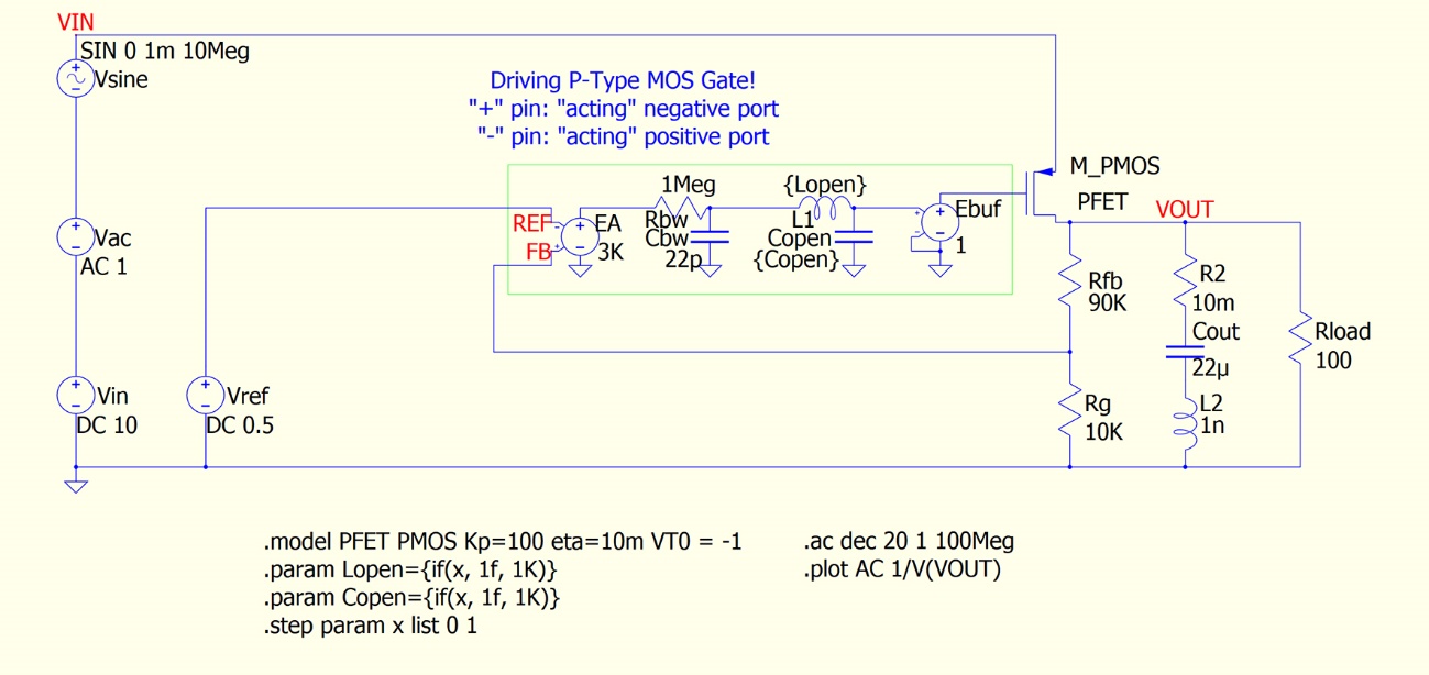
Figure 2. LDO example simulation for PSRR bandwidth evaluation
The LC pair ‘Lopen’ and ‘Copen’ work to open/close the loop control. When ‘closed’ at x=0, the gate drive signal from the error amplifier connects to the P-FET. When ‘open’ at x=1, the gate drive signal from the EA goes through a strong low-pass filter and only the DC bias point is set by the EA. When the EA is ON, we have our normal-looking PSRR curve. When OFF, what we see is an output capacitor as a passive filter.
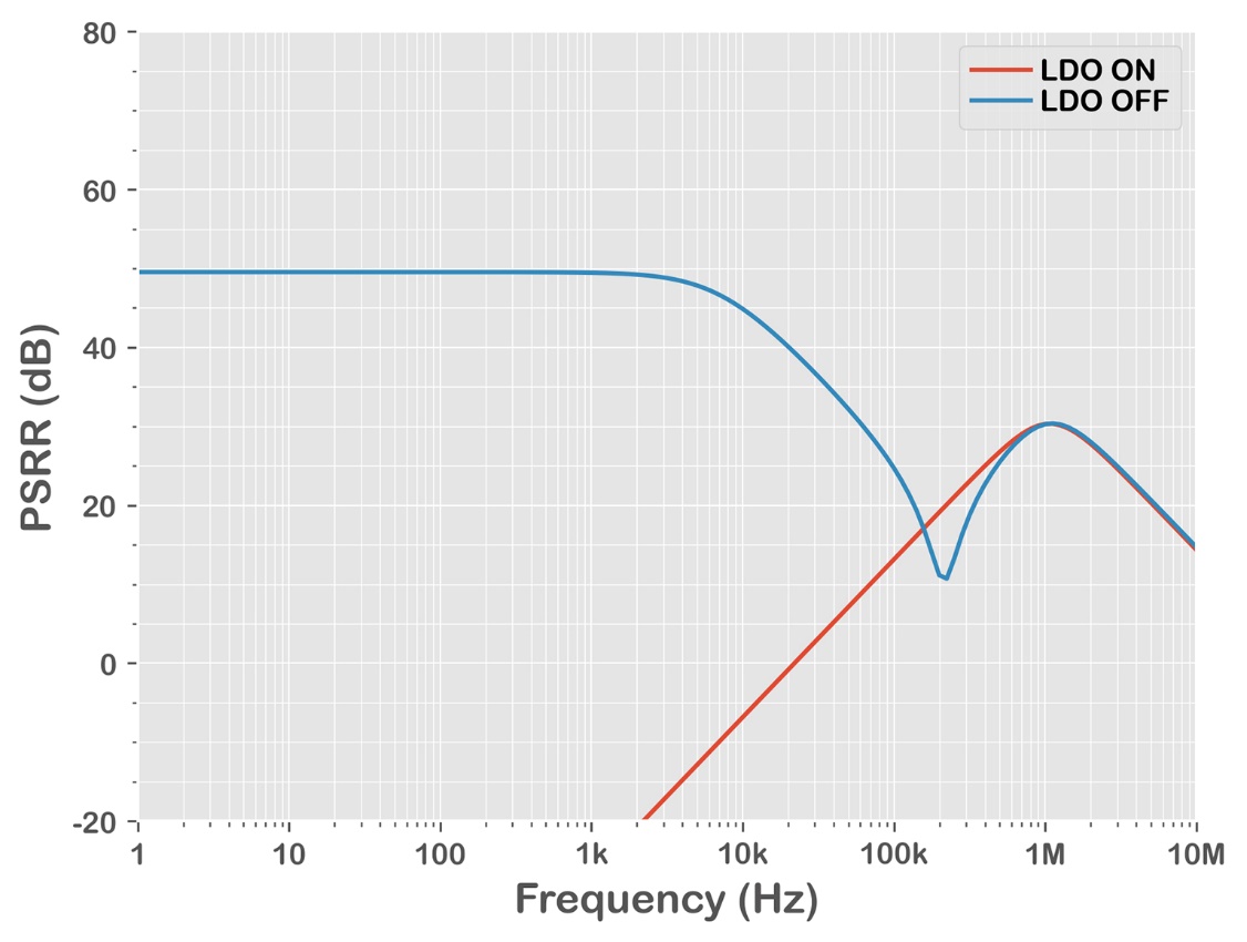
The model illustrates that the PSRR curve of a regulator beyond its loop bandwidth is a characteristic of the output capacitor. As we modeled this output capacitor to have ESR and ESL, it has its self-resonant peak that helps to boost the PSRR. However, again, that is nothing to do with the LDO control loop.
This simulation model represents the typical PSRR performance of many LDOs in the market. Except for some very high-performance devices, in general, a VRM only provides meaningful PSRR filter benefits up to around 100 kHz. If your frequency of concern is beyond 100 kHz, you need to take a deep breath and ask yourself if regulator PSRR performance is a significant design element in your system.
There are many power system diagrams showing an LDO intended to clean up ripple and noise from a switching regulator as in the drawing below. Nowadays, we can find great performance controllers, inductors and capacitors allowing switching regulators to operate beyond 1 MHz. So, to switch ripple clean-up, our frequency of concern can be 1 MHz or higher - you need to find a very wide control bandwidth LDO to achieve your goal and I say ‘good luck finding such a good LDO within your budget’!
We continue our review of PSRR performance in the following blog posts and ask the question:
‘Can an LDO filter switching regulator ripple’ as shown in Figure 4?