This application note covers power handling capability of coaxial cables. The matrix of average power over frequency provided for each example cable type is to be used as a guideline.
Peak and average power
There are two potential failure modes in cables used to transmit high peak power. One is voltage breakdown; the other is overheating. The major concern associated with application of peak power is breakdown due to high potential. By themselves, the cable and the connectors may break down under high voltage due to peak power. However, the cable-to-connector junction is the one location on the cable assembly most sensitive to high potential breakdown. Prudent design of overlapping dielectrics and proper selection of connector type, combined with actual high potential or severe requirements testing, ensures that breakdown will not occur. Another consideration in pulsed systems is overheating due to CW power.
Average (CW) power handling capability
The major effect of average power in cable assemblies is the generation of heat from power dissipation and the resultant temperature rise. Many factors are involved in determining this effect for a particular cable assembly, but a short discussion may help distinguish the many facets of the problem.
In all cases, the limit of CW power level is reached when the hottest surface temperature (measured anywhere on the cable assembly) has reached a predetermined temperature, Tmax. For most high performance high power cable assemblies, Tmax is on the order of 400°F (204°C). This temperature is chosen based on explosive atmosphere mil spec requirements and also because higher temperature starts to soften the dielectric used in most cables. The temperature Tmax usually occurs near or on the connector nearest the source. For different types of cables, the tolerance temperature unit that a component within that cable will withstand determines Tmax. Expressed differently, one may allow Tmax to increase up to the limit of initial damage to the most sensitive component within the cable.

Connectors as a limiting factor
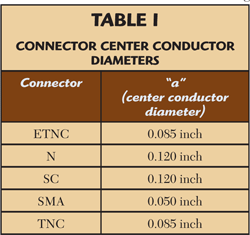
Heat generation in a connector is analyzed by examining the center conductor diameter "a" of the connector involved (see Table 1). Generally, if the diameter of the center conductor of the cable is approximately the same as the dimension "a" of the connector, the surface temperature at the connector and of the cable next to it will be about the same with power applied. Choice of a small connector for use with a large cable will make the connector hotter than the cable.
The data presented includes a safety margin (SM). This SM will allow operation of cable assemblies at the stated average power levels for the length of time called out in the appropriate mil specs.
Aging is a process dependent on many variables; among them are ambient temperature, mechanical vibration or flexure, and handling. If one could isolate the aging effect due to the application of power only, the following applies (as for all microwave components): there is a time limit, after which continuing the application of CW power will accelerate the aging of the cable assembly. Power application eventually will affect cable performance. These time limits will vary, depending on consideration of all stresses.
Heat removal
The following is a discussion of heat removal and experimental results obtained at Cobham. Exact mathematical description of the hot cable assembly in terms of heat flow analysis is almost impossible.
Under steady state conditions (typically achieved after about 20 minutes of continuous CW power application), a cable assembly has a unique temperature distribution. This distribution is heavily influenced by the installed environment. As in all heat transfer problems, the hot cable assembly gets rid of its heat by conduction, convection and radiation. Conduction could be the most effective of the three, especially at high altitude where the air is thin. However, because the geometry of bulkheads and mounting plates in general cannot be predicted, this most effective means of heat removal is not included in the power handling data. In fact, the power handling data relates to a cable that is allowed only convection and radiation for heat removal. While conduction might improve significantly the power handling characteristics of cable assemblies, this note treats any benefit resulting from conduction as an increased safety margin.
Of the two means left for removing heat, convection remains as the more effective, even at high altitude. Cobham has empirical data based on extensive testing of many cable assemblies in the companyís temperature-altitude chamber, while varying the chamberís ambient temperature and altitude. These tests were performed on a variety of cable types to generate the power handling and derating the data. The matrix data are a good guide to choosing the right cable for a particular frequency and average power level (see Figure 1).

Practical consideration
A system application may require all cable assemblies to use ETNC connectors. In addition, the cable chosen may have a center conductor considerably larger than that of the connector. When this is true, the connector will be hotter, perhaps considerably hotter, than the cable. Under these conditions, heat sinking of the connector is recommended; bulkhead connectors or finned heat-sunk connectors are examples of such connectors. Usually, heat sinking is sufficient since conduction is very effective at removing heat. However, if power levels and predicted temperatures are very high, tests should be conducted to verify the design.
Approximate derating curves
To determine the Derating Factor (DF) at different altitudes or at different ambient temperatures, see Figure 1. Based on the listed groups, select the appropriate derating curve. Multiply the average power handling data at the frequency of interest. The resultant number is the maximum average power handling capability of the selected cable at the selected ambient temperature and altitude (Derated Average Power = DF x Average Power from data section).
