Coaxial cable derives its name from the spatial relationship shared between the center conductor and the outer conductor. Figure 1 shows this "co-axial" positioning of conductors. A British engineer and mathematician by the name of Oliver Heaviside first patented the basic design of coaxial cable in 1880 (Patent Number: 1407). Then in 1929, almost 50 years later, Lloyd Espenshied and Herman Affel of AT&Tís Bell Labs secured a United States patent for the first modern coaxial cable design (US Patent Number: 1,835,031). Soon afterwards, coaxial cable started gaining popularity with radio engineers and became the preferred choice for connecting antennas to transmitters and receivers. As it turns out, coaxial cable is well suited for running up and down metal antenna towers, along gutters, or around any other metal structures since all electrical energy transmits down the interior of the cable and remains isolated from external influences.

Figure 1 Center and outer conductor alignment along a common axis.
In the late 1920s and early 1930s, Bell Labs set out to determine which coaxial impedance value was optimum. Surprisingly, the optimum impedance changes depending on the primary application. By experimentation Bell Labs found 30 ohms is best for high power, 77 ohms is best for low attenuation, and for high voltage 60 ohms turned out to be the best impedance value. Most modern coaxial cables come in 50, 75 or 93 ohm impedances and 50 ohms is by far the most popular impedance choice for high frequency transmission lines.
Although other industry standards have come and gone since the 1930s, MIL-C-17, now called MIL-DTL-17, has become the most comprehensive and most referenced coaxial cable standard. Three examples of how this military standard impacts our daily lives are:
- Cable Television: The National Cable & Telecommunications Association most recent statistics identify 104.7 million CATV subscribers in the United States. The majority of those households receive their video transmissions through a M17/2 - RG6 cable.
- Vital Emergency Services: M17/28 ñ RG058 remains one of the most widely used 50 ohm radio antenna cables. It is used on most two-way radio communications systems, such as CB radios, police, fire, ambulance and marine radios.
- A recent GOOGLE web search for "MIL-C-17" produced over seven million references.
We see that many times a day our lives benefit from MIL-DTL-17 cables, but when it comes to transmitting frequencies above 12 GHz, designers must turn to modern cable designs that far exceed the performance specifications of M17 cables. When working at higher and higher frequencies the question we have to ask is, "What is the optimal cable choice for my application?" The following discussion seeks to answer this question by looking at various cable constructions.
Optimal Coaxial Cable Constructions
Coaxial cable design choices include physical size, frequency performance, attenuation, power handling, flexibility, strength, environmental conditions and cost. Todayís engineers and designers can choose from a wide variety of design and construction choices, each having their own benefits. The common components found in every coaxial cable include the inner conductor, the dielectric, the outer conductor and the jacket. Each of these components can employ production methods, design innovations and material technologies that optimize specific mechanical and electrical properties, but choosing to boost performance in one area often means reducing performance in another. The following discussion will explain this give and take with regard to performance specification, and provide guidance in making the right choices to successfully match a coaxial cable transmission line to an application.

Figure 2 Basic coaxial cable construction.
Inner conductor design choices impact the cableís life span when subjected to dynamic flexure. They also largely influence the attenuation performance (see Figure 2). Basic design choices include the number of strands that make up the conductor and the base metal and surface plating. There are other conductor options, but most high frequency cables use these standard wire constructions for inner conductors including single strand (solid), 7 strands, 19 strands and 37 strands. As a general rule of thumb, the more strands a conductor has the more flexible it will be and the longer its dynamic flexure life will extend. However, the down side to increasing the flexibility of the conductor is that the attenuation caused by the conductor also increases. The designer sacrifices attenuation performance for better flexure performance.
Table 1 lists general data pertaining to the dynamic flexure life of copper conductors with various stranding factors. This data was derived experimentally on a MIL-T-81490 flexure test fixture and is offered for reference only since dynamic flexure life depends on bend radius, angular deflection and the rate of flexures per minute.

In addition to the number of strands contained in the center conductor, the base metal or surface plating conductivity can significantly affect the attenuation of high frequency coaxial cables. A phenomenon known as "skin effect" allows cable designers to take advantage of thin surface layers of highly conductive metals such as silver to minimize cable attenuation. Even though silver is expensive, a relatively thin layer of plating provides significant improvement in loss. Figure 3 shows the effective skin depth of electrical energy traveling in on a copper conductor between 10 MHz and 40 GHz. Above 10 GHz the skin depth is less than 1 micron, which demonstrates a 40 micron thickness of silver plating over the copper will carry all of the electrical energy and reduce the overall conductor losses.

Figure 3 Skin depth calculations for a copper conductor.
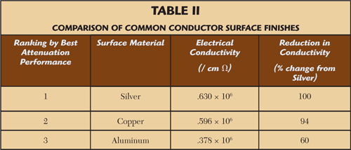
Table 2 shows the conductivity of the most common conductor surface plating used in high frequency cables and coaxial connectors, ranked from best to worst. Although silver plating offers better conductivity, it also costs significantly more than copper or aluminum; both cost and attenuation performance must be considered when choosing the optimal conductor finish. Taking advantage of skin effect at microwave frequencies, however, means the plating thickness can be relatively thin, which helps control costs.

To summarize, multi strand center conductors offer much better flexure life, but sacrifice attenuation performance compared with a solid conductor. Consideration must be given as to whether attenuation or flexibility is most important before selecting the best cable construction for any given application. Also, most high frequency coaxial cables employ silver plated conductors because the conductivity of silver is better than aluminum or copper, and the skin effect at high frequencies enables thin layers of silver plating to add substantial performance benefit.
Dielectrics provide an insulating layer between two conductors and, in the case of coaxial cables, also perform an important mechanical function by supporting the outer conductor and keeping both conductors fixed along their common axis. Dielectrics used in manufacturing high frequency coaxial cables have two very important characteristics: low dielectric constants and low dissipation factors.
The dielectric constant (k) of a material is used to determine that materialís ability to carry alternating current when compared to air in a vacuum. A vacuum provides the most efficient means of transmitting electrical energy and has a k of 1.000. All other materials have higher values for their respective dielectric constants. Values for the most common coaxial cable dielectrics are shown in Table 3. To minimize power losses it is always desirable to have the lowest possible dielectric constant in high frequency coaxial cables.

Dissipation factor is a measure of the inefficiency of a dielectric material. All dielectrics dissipate electric power in the form of heat because of their inefficiencies and the more inefficient a dielectric is, the higher its dissipation factor will be. Table 3 shows comparable dissipation factors for dielectric materials used in high frequency coaxial cables. To minimize power losses, it is always desirable to use materials with the lowest possible dissipation factors.
As shown in Table 3, air in a vacuum provides the optimal dielectric material for transmitting electrical energy. However, air does not provide the mechanical support required to keep the center conductor and outer conductor of a coaxial cable fixed in place. The next best material, which does provide the needed mechanical strength for flexible cables, is a low density Polytetrafluoroethylene (PTFE). Low density PTFE is also referred to as "expanded" or "microporous" PTFE throughout the RF and microwave industry. These terms all describe the same type of material that is standard PTFE with microscopic air spaces distributed throughout. The more air spaces in the material the lower the density and the better the electrical performance of the composite dielectric. This results in a dielectric material, which has a lower dielectric constant and dissipation factor than solid PTFE but still has enough strength to provide a stable mechanical structure to support both conductors.
The top manufacturers of low loss, high performance cables utilize low density PTFE exclusively in their cable constructions for the reasons listed above. GORE‘ expanded PTFE and DynaCore‘ low density PTFE dielectrics are two examples of how this material technology is applied in coaxial cable products.
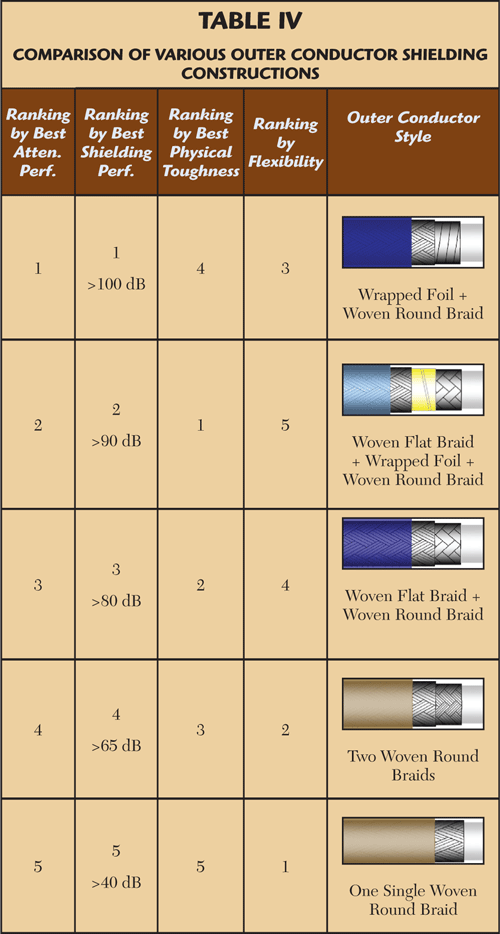
Outer conductor or shield choices impact the attenuation, shielding effectiveness, physical resistance to torque and crushing, and the flexibility of coaxial cables. Basic design choices include braid coverage, application of braid by weaving or wrapping, total number and combination of braid and foil layers, and base metal and surface finish.

There are a variety of ways to design and manufacture shields on coaxial cables. Flexible cables use any combination of braided fine wires and wrapped foils to provide a conductive layer that flexes. Table 4 shows five different variations of outer conductor designs for flexible cables ranked by different design considerations.
Jacket materials serve as a protective covering from the environment. Although cable jackets do not play a role in the electrical performance of a coaxial cable, they are an integral part of the overall cable performance when installed. Some of the environmental conditions cable jackets are designed to protect against include extreme temperature excursions, abrasion, ultra violet radiation, rain, humidity, flame resistance, low smoke and toxicity, resistance to fluids, crushing/bending forces and corrosion. There are various jacket materials offered by manufacturers that are tailored to protect against one or more of these types of environmental conditions. Most manufacturers offer guidance on jacket choices and designers need to consider the service environment their products will experience when choosing the optimal cable for their application.
Conclusion
It has been 130 years since Oliver Heaviside first patented the concept of coaxial cable in 1880. Another 80 years have passed since the pioneering work at Bell Labs laid the groundwork for modern coaxial cables to be defined by 50, 75 and 93 ohm impedances and standardized by the military specification, MIL-DTL-17. Today our lives are impacted in many ways by coaxial transmission lines. They are used extensively in two-way communications systems for police and fire departments, rescue personnel, and first responders. The products we consume every day are shipped on carriers who rely on satellite communications systems, GPS tracking and mobile telecommunications technology that all operate with the aid of coaxial cable transmission lines. Our national security is also supported by communication systems, radars, electronic counter measures and target acquisition systems that use coaxial cables.
In the last 30 years a large push to transmit at higher frequencies challenged the manufacturers of high performance coaxial cable to push the technology and introduce new products. These new cables far exceed the performance standards of MIL-DTL-17 and well informed engineers can take advantage of a variety of product designs and innovations to optimize critical performance parameters in their system designs. No single cable offers the best solution for every design application, but by carefully considering the various material and design options related to the inner conductor, dielectric, outer conductor, and jacket and how those options impact the coaxial cableís electrical, mechanical, cost and environmental performance, the optimal product choice can be made.
