Highly accurate microwave systems derive their frequency stability from lower frequency reference oscillators, crystals or atomic standards. The resulting phase noise is, ideally, the lower frequency reference oscillator noise multiplied by 20 log N, where N is the frequency multiplication factor. In microwave systems, this factor can be very significant and mandates the use of a very low noise reference (for example, a Ku-band system will typically have a 12 GHz final local oscillator signal derived from a 10 MHz reference, increasing the reference phase noise by 20 log [12000 MHz/10 MHz] = 61.6 dB). The use of phase-locked loop multipliers can mitigate some of this increase in phase noise because the phase-locked loop acts as a narrow band filter around the carrier. The single sideband filter bandwidth equals the phase-locked loop bandwidth, usually 10 to 100 kHz. The phase noise beyond the loop bandwidth is the attenuated multiplied reference plus the phase noise of the phase-locked microwave source. The phase noise of the microwave source closer to the carrier than the phase-locked loop bandwidth is attenuated by the phase-locked loop. This is summed with the multiplied reference noise to attain the total phase noise in this region. The total composite phase noise of the system is the sum of the resultant noise from each of these sources.

Fig. 1 Phase noise of the frequency converter and the external 10 MHz reference.
Determining the total composite phase noise is a complex calculation requiring knowledge of the phase noise of the reference and microwave oscillators, the reference multiplication efficiency factor (usually 1 to 3 dB above the ideal 20 log N factor) and the phase-locked loop frequency response (the output noise (?out) as a function of the noise injected at the reference (?ref)) and the noise injected by the microwave oscillator (?micro). The purpose of this article is to show that the complexity of these calculations can be drastically reduced while maintaining a reasonable accuracy knowing as few parameters as:
• The frequency and phase noise of the reference oscillator.
• The frequency and phase noise of the microwave oscillator.
• The loop bandwidth of the phase-locked loop.
Reducing the complexity of the calculation is accomplished by making a few assumptions in the other stated characteristics. These assumptions are close enough to the actual characteristics to maintain a reasonable degree of accuracy:
• Assume a second-order phase-locked loop with one zero (probably the most common configuration).
• Assume a damping factor of 1. This is a reasonable compromise, which equates to a maximum rejection and minimal phase noise peaking.
Phase Noise Analysis
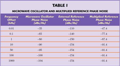
A general procedure for determining the total composite system phase noise is described in the following example. Figure 1 shows typical phase noise values of a microwave local oscillator at 12 GHz and a high stability 10 MHz reference. The microwave oscillator will be phase-locked to the 10 MHz reference.
The multiplication factor is N = 12 GHz/10 MHz = 1.200 and 20 log (1200) = 61.6 dB. Including the 1 dB multiplication efficiency factor, the added phase noise is 62.6 dB. Table 1 shows the microwave oscillator and the multiplied reference phase noises. Figure 2 is a plot of the phase noise of the multiplied reference and the microwave local oscillators. The phase noise plots cross at an offset frequency of nominally 15 kHz. This cross over is the optimum setting for the phase-locked loop response. It is therefore reasonable to assume that the 3 dB phase-locked loop bandwidth will be set at 15 kHz. The multiplied reference oscillator phase noise is attenuated for offset frequencies above 15 kHz and the microwave oscillator noise is attenuated for offset frequencies below 15 kHz. The magnitude of the attenuation is determined by analyzing the phase-locked loop output noise response, with respect to the reference and microwave oscillators noise.
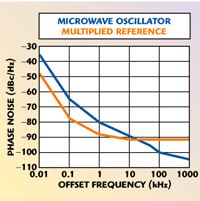
Fig. 2 Phase noise of the frequency converter and the multiplied external 10 MHz reference.
The block diagram of Figure 3 is a representation of a typical microwave oscillator, phase-locked to a low frequency reference oscillator. H(s) is typically a pole and a zero such that the frequency response of the output phase noise (?out) as a function of input phase noise (?ref) is

where
S = j? (radian/sec)
?n = 2?Fn, and Fn is the loop bandwidth in Hz
? = damping factor (usually 0.7 to 1.5 for minimum noise peaking)
This function contains two poles and one zero. Since the zero is of the same order of magnitude as the poles, the magnitude of the frequency response far away from the cut-off frequency will be expected to decrease at a rate of 20 dB per decade even though it is a second-order phase-locked loop. Often, additional poles are added at higher frequencies (at least ten times the loop bandwidth) to provide greater than 20 dB per decade phase noise rejection.
The output phase noise (?out) as a function of microwave oscillator noise (?micro) has the following frequency response:

This function, with effectively a two-pole high pass filter response, decreases at a rate of 40 dB per decade significantly below the cut-off frequency.

Fig. 3 Block diagram showing noise injection in a typical phase-locked loop.
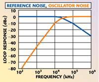
Fig. 4 Pahse-locked response.
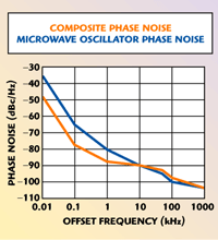
Fig. 5 Composite phase noise and microwave source phase noise.
Figure 4 is a plot of a typical normalized loop response with respect to the reference oscillator phase noise and the microwave source phase noise. Table 2 shows the reference and microwave oscillators phase noise, attenuated by the loop responses described above, with the damping factor (?) equal to 1 and a loop cut-off frequency (Fn) equal to 15 kHz.
The composite phase noise (Pout) is a summation of the phase noise power of the reference (Pref) and the microwave oscillator (Pmicro), taking into account the effects of the phase-locked loop.

where
Pout = total composite noise power at a particular offset frequency
Pref = multiplied phase-locked reference noise power at the same offset frequency
Pmicro = phase-locked microwave oscillator noise power at the same offset frequency
Figure 5 shows a graph of the composite phase noise (total output phase noise, Pout) compared to the original microwave oscillator phase noise. Note the decrease in the phase noise close to the carrier. There is a slight increase in phase noise near the phase-locked loop bandwidth due to the fact that the reference phase noise is attenuated by only 20 dB per decade.
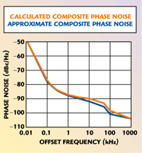
Fig. 6 Comparison of approximation vs. actual composite phase noise.

Quick Approximations Assuming an Ideal Loop Filter Response
A quick approximation of the total composite phase noise can be made by assuming that the loop response of the filters are ideal, that is the reference phase noise does not exist for all frequencies greater than the loop bandwidth and the microwave source phase noise does not exist for all frequencies less than the loop bandwidth. Figure 6 shows the comparison of actual phase noise calculated versus a quick approximation of the phase noise using ideal loop filters. The error is shown in Table 3.
If a data point is at the loop bandwidth, the phase noise is the composite value as previously calculated with 3 dB subtracted from each source to account for the nominal 3 dB rejection at the cut-off frequency.

where
Ptot3dB = total composite noise power at the phase-locked loop bandwidth
Pref3dB = multiplied reference noise at the phase-locked loop bandwidth
Pconv3dB = converter noise power at the phase-locked loop bandwidth

Occasionally, the externally provided reference oscillator, while being very stable (long-term average), has a poor short-term stability (phase noise). This situation is usually resolved by using a clean-up reference oscillator. The noisy input reference is phase-locked to a very low noise internal crystal oscillator. This has the effect of multiplying the phase noise of the internal reference oscillator beyond the loop bandwidth while maintaining the long-term stability of the external reference. The effect on total system phase noise is the same as previously calculated except that the loop bandwidth is on the order of 50 to 200 Hz.
Changing the Reference Oscillators
Many times, the system phase noise is given with an internal reference oscillator or a test oscillator used as a reference for measurement purposes. When this oscillator is being substituted for an external reference oscillator, the effect of the original oscillator must be removed from the composite system phase noise before the effect of the external reference oscillator is determined.
The basic parameters necessary for this calculation are:
• Reference frequency
• Output frequency
• Frequency response of the phase-locked loop
• Multiplier efficiency
• Phase noise of the composite system
• Phase noise of the reference oscillator used to measure the composite phase noise
• Phase noise of the external reference oscillator used in the final system configuration
Assuming the phase-locked loop has a second-order response with a damping factor of 1 simplifies the analysis. The error introduced will probably be small. Aside from knowing the frequency and phase noise of the respective oscillators the only additional information needed is the loop bandwidth. The basic procedure for performing this analysis is as follows:
• Determine the phase noise of the measurement reference oscillator.
• Multiply the reference oscillator noise to the microwave frequency, Pref (adding the multiplication efficiency factor, typically 1 dB).
• Analyze the frequency response characteristics of the phase-locked loop, the output phase noise (?out) as a function of input phase noise (?ref) and calculate the resultant phase noise (Equation 1).
• Subtract the results, data point by data point, at each respective offset frequency from the system phase noise Pout (Equation 5). The result is the phase noise of the microwave source Pmicro attenuated by the phase-locked loop.

• The stand-alone phase noise of the microwave source is obtained by multiplying Pmicro by the magnitude of the inverse of the phase-locked loop frequency response. The microwave oscillator noise (?micro) as a function of output phase noise (?out) is given in Equation 6.

• When the results are in decibels, simply subtract the phase-locked loop frequency response at the respective offset frequency. The result is the phase noise of the microwave source without the effect of the phase-locked loop.
• The resultant phase noise characteristic is used as previously described to calculate the total system phase noise with respect to a new reference source.
Table 4 shows a numerical example of how to remove the effects of the reference phase noise from the total system or microwave oscillator phase noise. The system parameters necessary to perform the calculation in this example are:
• Reference frequency: 10 MHz
• Output frequency: 12,000 MHz
• Loop bandwidth: 15 kHz
• Multiplier efficiency factor: 1 dB
It is assumed that the phase-locked loop has a typical second-order response characteristic.

Column 1 is the frequency offset from the carrier. Columns 2 and 3 are the total system phase noise in dBc/Hz and the reference oscillator phase noise contained in the total system phase noise, respectively. Column 4 is the multiplied reference phase noise (20 log N) with the added multiplier efficiency factor of 1 dB. The effect of the phase-locked loop frequency response is subtracted from the multiplied reference phase noise (Equation 5) in column 5. In column 6, the results from column 5, the net effective reference phase noise, are subtracted from the phase noise of the microwave source. This result is the microwave source phase noise attenuated by the phase-locked loop. The actual microwave source noise is the result found in column 6 minus the effect of the phase-locked loop frequency response in Equation 1. This result, given in column 7, is the actual system phase noise prior to being attenuated by the phase-locked loop. This is the microwave source phase noise that should be used to determine the system phase noise characteristic when the microwave source is being phase-locked to an external reference.
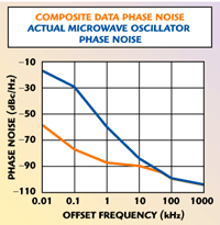
Fig. 7 Composite phase noise and actual microwave source phase noise.
Figure 7 is a comparison of the total composite system phase noise and the noise of the microwave oscillator before being phase-locked to a low phase noise reference.
Conclusion
The microwave oscillator phase noise, the multiplied reference phase noise and the phase-locked loop frequency response determine the total composite phase noise in a system. When a microwave oscillator is phase-locked to a low frequency, low phase noise reference, the phase noise from the microwave oscillator exists below the offset frequency equal to the loop bandwidth and the multiplied reference phase noise exists above that frequency. Some simple calculations can be used to determine the total system composite phase noise, including the effects of the residual phase noise on either side of the loop bandwidth (offset frequency with respect to the carrier) with sufficient accuracy for most applications. Although the phase-locked loop bandwidth is not a barrier frequency with a discontinuity on either side of the barrier, it can be approximated as such with the proviso that small errors around the offset frequency equal to the loop bandwidth are accepted.
References
1. F.M. Gardner, Phase-lock Techniques, John Wiley & Sons Inc., Somerset, NJ.
2. P.V. Brennan, Phase-locked Loops: Principles and Practices, McGraw-Hill, New York, NY.
3. R. Best, Phased-locked Loops: Theory, Design and Applications, McGraw-Hill, New York, NY.
