 RF engineers are primarily concerned with real signal power when sizing components and implementing controls for optimization of signal fidelity and/or data integrity. In communication links, RF signal power is carefully managed to maintain high performance and reliable connections over some distance. Transmitters carefully monitor signal power to maintain high levels of efficiency, and conformity to spectral regulations. Receivers monitor signal power to maintain optimal sensitivity and selectivity.
Most every power detector available on the market has been designed for broadband communications systems. However, it is the manufacturers of test equipment, developers of military and space technology, and advanced physics labs that have challenged companies such as Hittite Microwave Corp. to develop power detector technology best suited for measurement performance in terms of input sensitivity, dynamic range, repeatability, speed and accuracy over temperature. The HMC614LP4E RMS Power Detector with iPAR is the latest outcome of that work.

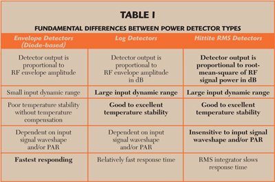
Table 1 Fundamental Differences Between Power Detector Types
In general, power detectors sense an RF signal and produce an output signal that corresponds to that level of signal energy. A subsequent processor takes that detector output and correlates it to real signal power. Log detectors and RMS detectors have largely replaced diode detectors for large dynamic range applications, but each type has characteristics that lend themselves better to some applications than others. Table 1 provides a comparison between power detector types (key advantages of each detector type are indicated in bold).
Log Detectors
Log detectors work well for systems in which the RF signal is pulsed (such as TDMA systems) and/or when the signal’s peak-to-average power ratio (PAR) remains relatively constant. The output of a log detector correlates well with real signal power; however, that correlation varies as wave-shape and PAR vary.
The latest generation of broadband communication systems employ complex modulation schemes and sophisticated spread-spectrum techniques often producing signals with PAR fluctuating over time, occasionally rising to high levels. These “peaks” in the amplitude-modulated (AM) RF envelope introduce an error on the log detector’s output. In contrast, true RMS power detectors are not afflicted with the same weakness. RMS power detectors maintain an accurate read of average signal power regardless of RF signal wave-shape or PAR. However, RMS detectors are relatively slow when compared with their faster responding siblings.

Figure 1 RMS Detector output voltage vs. input signal power.
RMS Detectors
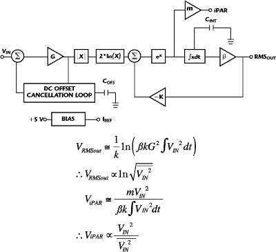
True RMS detectors are in effect analog calculators, calculating RMS power of the input signal, unlike other types of power detectors that are designed to respond to the RF signal’s AM envelope. At the core of an RMS detector are a full-wave rectifier, log/antilog circuit and an integrator. The RMS output signal is directly proportional to average input signal power expressed in dB. The bias block also contains temperature compensation circuits that stabilize output accuracy over the entire operating temperature range. The DC offset cancellation circuit actively cancels internal offsets so that even very small input signals can be measured accurately.
The “average” power indication from an RMS detector is well suited for signal level and gain control. However, it is often critically important to be aware of other details of RF signal characteristics beyond average signal power. For example, continuous monitoring of peak signal power is often necessary to avoid overdriving signal chain components into saturation. Similarly, monitoring signal crest factor for a radio transmitter enables efficiency controls on the power amplifiers. Every traditional approach to this problem has employed two separate power detectors operating in parallel: an RMS power detector and an envelope detector.

Figure 2 HMC614LP4E RMS Detector with iPAR behavioral model.
Two Simultaneous Outputs from the Same Measurement Structure
A new type of power detector, the HMC614LP4E, now combines the strengths of both envelope detectors and RMS detectors. At the front-end of an RMS power detector is an envelope detector, which then feeds into an analog RMS processing circuit. Looking deeper within Hittite’s RMS detector, there is a signal that correlates to instantaneous envelope power normalized to average power, or in other words envelope-to-average power ratio. That signal is buffered and brought to the outside world as “iPAR”, alongside the RMS output.

Table 2 HMC614LP4E Key Specifications
Thus, this same power detector produces two simultaneous outputs from the very same measurement structure. Furthermore, a simple peak-hold capacitor on the iPAR output produces a peak-to-average power ratio output. Hittite’s HMC614LP4E RMS Detector with iPAR combines all of the benefits of an RMS power detector, with the iPAR output providing the speed of an envelope detector. The simultaneous detector outputs provide a read of peak signal power, average power, peak-to-average power ratio and RF wave-shape. Key performance specifications of the HMC614LP4E RMS Detector are shown in Table 2.
Traditional RMS measurement solutions employ two separate detectors that require two separate sets of calibration factors over temperature and, consequently, correlation between detector outputs can become a complex problem. The iPAR solution has the fundamental advantage of using the very same measurement and compensation structures as the RMS detector, so the HMC614LP4E iPAR output is intrinsically normalized to RMS power. The iPAR output can be configured in one of two ways: iPAR can either track the instantaneous RF signal envelope power, or iPAR will indicate peak envelope power (with a peak-hold capacitor on the iPAR output pin). iPAR is brought out as a relative reading, rather than as an absolute reading of signal power. iPAR is normalized to RMS signal power thereby providing two distinct advantages over the two detector traditional approach:
- The iPAR output is independent of average signal power (over a very large range)
- With two separate power detectors, the absolute readings provided by each detector must always be made to fully correlate over input signal frequency and over temperature (Hittite’s iPAR solution eliminates the struggle of correlating two different detector types). Since the HMC614LP4E RMS and iPAR outputs share the same measurement and compensation structures, they are well correlated over signal frequency and temperature
As mentioned previously, the averaging operation within the RMS detector slows its response. The averaging time-interval is set by the user using an external “integration” capacitor (CINT). RMS detector measurement accuracy requires a compromise between the averaging time-interval and output transient response. Larger values of CINT will correspond to a longer averaging time-interval; however, it will also slow the power detector’s transient response favoring detector output accuracy over speed. Conversely, a smaller value of CINT will favor detector speed over measurement accuracy.
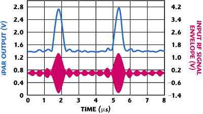
The HMC614LP4E iPAR output, however, responds very quickly, as it is not hampered by the RMS integration function. iPAR provides a real-time indication of RF signal power envelope:


Figure 3 HMC614LP4E iPAR output.
Conclusion
Hittite Microwave has developed a new type of RMS power detector, the HMC614LP4E, which combines the benefits of both envelope detectors and RMS detectors to provide an indication of average power, instantaneous envelope power ratio and peak-to-average power ratio. The HMC614LP4E operates from 0.1 to 3.9 GHz with up to 71 dB of input sensing range (to ±1 dB measurement error). This RMS detector is ideally suited to many wide bandwidth, high dynamic range applications requiring repeatable measurement of real signal power, especially where the RF/IF wave-shape and/or crest factor change with time.
Hittite Microwave Corp.,
Chelmsford, MA (978) 250-3343,
www.hittite.com
RS No. 303
