A novel CPW-fed rectangle-trapezoid-rectangle shaped monopole antenna composed of a trapezoid and two rectangles is presented. In this context, the flat monopole structure improves the impedance bandwidth and reduces the size of the antenna dramatically. The ultra-wideband (UWB) antenna design plays a role as a filter. The coplanar waveguide grounds are beveled and the impedance transformer patch (ITP) performs a 50 to 100 Ω impedance transformation. The impedance and radiation characteristics of this antenna are studied. The measured bandwidth, defined by a 10 dB return loss, is from 2.78 to 10.71 GHz. The overall size of the printed antenna is 31.45 x 31.45 x 0.8 mm, which is very compact, low profile and can be integrated within an ultra-wideband transceiver. The proposed antenna also has the advantages of a very simple geometric structure, good radiation characteristics, almost omni-directional radiation patterns and smooth gain characteristics. Therefore, it is a good candidate for ultra-wideband applications.
Ultra-wideband technology has been widely used in various wireless communications and has attracted much attention recently for communication systems. UWB is suitable for high-speed wireless communications within Wireless Personal Area Network (WPAN), because of its short-range, high data-rates, low-cost and low-power technology, utilizing the unlicensed radio spectrum from 3.1 to 10.6 GHz. The design of a UWB antenna is one of the most exciting tasks in these systems. Some coplanar waveguide (CPW) antennas have been proposed for wideband applications.1–11
One of the critical issues in UWB system design is the size of the antenna for portable devices, because the size affects the wide impedance bandwidth, gain and omni-directional radiation pattern. Therefore, to miniaturize an antenna capable of providing a broad impedance matching bandwidth and an acceptable gain is a challenging task.4 To increase the bandwidth, such techniques as constructing a simple bevel,5 using a smooth rounded element6 or using a shorting pin7 have been reported. In addition, CPW-fed monopoles1–4 have also been introduced for their compact size, simple structure and ease of integration with microwave circuits.
In this article, a small size antenna is proposed using a CPW feed-line for UWB systems. Compared to the printed folded flared monopole antenna8 and the improved U-shaped stub rectangular slot antenna with a tuning pad for UWB applications,9 the proposed antenna can produce better gain and good radiation performance. This novel CPW-feed rectangle-trapezoid-rectangle shaped monopole antenna is composed of a trapezoid and a tangential rectangle. This monopole structure reduces the size, improves the impedance bandwidth and offers a smooth gain and almost omni-directional patterns. The detailed design and experimental results are presented and discussed in the following sections.
Antenna Design
The proposed antenna has a simple structure, with one layer of dielectric and metal. The antenna is fabricated on a low-cost FR-4 substrate with a dielectric constant εr = 4.4 and thickness h = 0.8 mm. The following design method has been used to develop the proposed CPW-feed antenna knowing the lowest frequency of the UWB operation (fL = 3.1 GHz) and the effective dielectric constant of the transmission line (εreff). Excluding the feeder, the width (W1) and length (L1) of the antenna structure can be calculated using Equations 1 and 2

where
c = speed of light in free space

Figure 1 Geometry of the CPW-fed UWB antenna.
The rectangle-trapezoid-rectangle shape is printed on a substrate L1 = 31.45 mm (0.3249 λ) by W1 = 31.45 mm (0.329 l) substrate, where λ is the free space wavelength at the 3.1 GHz frequency. The monopole antenna is fed by a 50 Ω CPW line with width W5 = 1.5 mm and a spacing gap G1 = 0.18 mm between the center conductor and the ground plane. The geometry of the proposed antenna is shown in Figure 1. The bevels in the ground plane enhance the operating bandwidth. The flare angle is θ = 45°.
In this article, the impedance transformer patch (ITP) is designed to obtain a well-matched wideband antenna. Recognizing that the center frequency for UWB operation is fr = 7.85 GHz and the dielectric constant is εr, the major ITP length (W6) and the width (L6) are chosen according to the following equations:

The ITP is formed by setting W6 = 4 mm. When the length of the W6 section increases, the ITP becomes a rectangle and the bandwidth increases gradually. The length of W6 controls the effective area of the rectangle and is the primary parameter to determine the coupling between the antenna element and the ground plane.
The rectangle-trapezoid-rectangle shaped patch is the radiator of the proposed design. The parameter LT = (L2 + L5 + L6 + L7) is used to control the impedance matching of the patch (LFIMP) at the lower frequency of operation and the width W2 influences the impedance bandwidth at the lower frequencies. The major length (LT) is chosen according to the following equation


Table 1 Dimensions of the CPW-Fed Rectangle-Trapezoid-Rectangle Monopole
Table 1 lists the antenna parameters of the proposed design. This antenna was constructed and experimentally studied.
Experimental Results and Discussion
To verify the performance of the proposed antenna, the prototype of the UWB antenna was measured after fabrication. The impedance bandwidth has been measured using the Agilent-8720ES vector network analyzer (VNA).

Figure 2 Measured return loss of the proposed antenna.

Figure 3 Measured return loss as a function of the ground plane bevel angle.
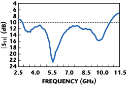
Figure 2 shows the measured return losses of the proposed antenna, which shows that a 10 dB bandwidth of 2.78 to 10.71 GHz has been achieved. The broadband of the rectangle-trapezoid-rectangle shaped monopole antenna is evident. This antenna has a matching impedance bandwidth that meets the requirements of the UWB band of 3.1 to 10.6 GHz. From the measured results shown, the length L2 of the LFIMP is approximately 0.1 times the operating center wavelength. In Figure 3, the impedance bandwidth is measured as a function of θ when the other antenna dimensions, L1 = 31.45 mm, L2 = 9.99 mm, L3 = 14 mm, L4 = 9 mm, L5 = 6.61 mm, L6 = 0.2 mm, L7 = 0.65 mm, W1= 21.86 mm, W2 = 19 mm, W3 = 5 mm, W4 = 10 mm, W5 = 1.5 mm, W6 = 4 mm, G1 = 0.18 mm, h = 0.8 mm and εr = 4.4 are kept constant. It shows how the return loss of the rectangle-trapezoid-rectangle shaped monopole varies with different ground plane bevel angles θ. It can be observed that this arrangement of the design leads to the enhancement of the impedance matching bandwidth as the bevel angle θ increases. It is observed that the angle of θ determines the impedance matching in the band of 4 to 5.5 GHz.

Figure 4 Measured return loss as a function of W6.

Figure 5 Measured radiation patterns in the x-z plane (E-plane).

Figure 6 Measured radiation patterns in the y-z plane (H-plane).

Figure 7 Measured gain of the proposed antenna.
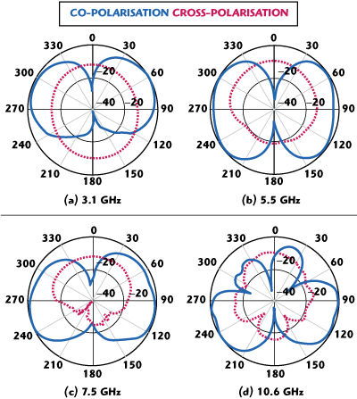
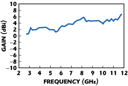
Figure 4 shows the return loss for different ITP lengths (W6), all other dimensions being identical to the previous figure. It is observed that the length of W6 determines the impedance matching in the band of 6.5 to 9 GHz. The radiation patterns of the proposed antennas at 3.1, 5.5, 7.5 and 10.6 GHz were also measured. Figures 5 and 6 show the x-z plane (E-plane) and y-z plane (H-plane) patterns, respectively. It is obvious that the radiation patterns are nearly omni-directional patterns and suitable for UWB applications. Figure 7 shows that the measured antenna gain, within the operating frequency band, is 2.5 to 5.6 dBi. The gain flatness of the proposed antenna is suitable for UWB applications.
Conclusion
A novel CPW-fed printed rectangle-trapezoid-rectangle shape antenna has been proposed. The proposed antenna, with a compact size of 31.45 x 31.45 x 0.8 mm, was implemented. It has a simple geometry, an effective feeding structure, an adequate operational bandwidth, a nearly smooth gain and has almost omni-directional radiation patterns. These features are very attractive for UWB applications and the antenna can be integrated in transceivers.
References
1. H.D. Chen and H.T. Chen, “A CPW-fed Dual-frequency Monopole Antenna,” IEEE Transactions on Antennas and Propagation, Vol. 52, No. 4, April 2004, pp.978–982.
2. D.C. Chang, J.C. Liu and M.Y. Liu, “A Novel Tulip-shaped Monopole Antenna for UWB Applications,” Microwave and Optical Technology Letters, Vol. 48, No. 2, December 2005, pp. 307–312.
3. W.C. Liu and P.C. Kao, “CPW-fed Triangular Monopole Antenna for Ultra-wideband Operation,” Microwave and Optical Technology Letters, Vol. 47, No. 6, October 2005, pp. 580–582.
4. S.W. Su, K.L. Wong and C.L. Tang, “Ultra-wideband Square Planar Monopole Antenna for IEEE 802.16a Operation in the 2 to 11 GHz Band,” Microwave and Optical Technology Letters, Vol. 42, No. 6, July 2004, pp. 463–466.
5. M.J. Ammann, “Control of the Impedance Bandwidth of Wideband Planar Monopole Antennas Using a Beveling Technique,” Microwave and Optical Technology Letters, Vol. 30, No. 4, July 2001, pp. 229–232.
6. N.P. Agrawall, G. Kumer and K.P. Ray, “Wideband Planar Monopople Antennas,” IEEE Transactions on Antennas and Propagation, Vol. 46, No. 4, April 1998, pp. 294–295.
7. M.J. Ammann and Z.N. Chen, “A Wideband Shorted Planar Monopole with Bevel,” IEEE Transactions on Antennas and Propagation, Vol. 51, No. 4, April 2003, pp. 901–903.
8. R.B. Waterhouse and D. Novak, “Printed Folded Flared Monopole Antenna,” Electronics Letters, Vol. 42, No. 3, February 2006, pp. 141–142.
9. D.C. Chang, J.C. Liu and M.Y. Liu, “Improved U-shaped Stub Rectangular Slot Antenna with Tuning Pad for UWB Applications,” Electronics Letters, Vol. 41, No. 20, October 2005, pp. 1095–1097.
10. C.H.K. Chin, Q. Xue, H. Wong and X.Y. Zhang, “Broadband Patch Antenna with Low Cross-polarisation,” Electronics Letters, Vol. 43, No. 3, February 2007, pp. 137–138.
11. K.P. Ray, Y. Ranga and P. Gabhale, “Printed Square Monopole Antenna with Semicircular Base for Ultra-wide Bandwidth,” Electronics Letters, Vol. 43, No. 5, March 2007, pp. 13–14.
Wen-Shan Chen received his BSc degree in electronic engineering of technology from the National Taiwan Institute of Technology (now known as the National Taiwan University of Technology) and his PhD degree from National Sun Yat-Sen University, Kaohsiung, Taiwan, ROC, in 2001. From 2001 to 2002, he was an assistant professor at the Chien-Kuo Institute of Technology, Changhua, Taiwan, ROC. He is currently an assistant professor in the department of electronic engineering of Southern Taiwan University, Tainan, Taiwan, ROC. His research interests include antenna design, RF and microwave circuits.
Kai-Cheng Yang received his MSc degree from the Southern Taiwan University of Technology, Taiwan, ROC, in 2005. He is currently a PhD student in the department of electronic engineering at Southern Taiwan University, Tainan Hsien, Taiwan, ROC. He is currently engaged in the development of ultra-wideband antennas and ultra-wideband systems. He has conducted research on ultra-wideband antenna characteristics in frequency and time domains. His current research interests focus on ultra-wideband antennas design, mobile small antennas and ultra-wideband systems.
