Editor’s Note: Part 1 of this tutorial appeared in the October issue of Microwave Journal. It addresses extracting DC diode parameters and using Excel to optimize the diode model. Part 2 addresses a similar methodology for AC parameters. Taken together, readers will get a simple, yet powerful tool for optimizing diode models.
Part 2 of this tutorial builds upon the process for extracting DC diode parameters presented in the October 2024 issue of Microwave Journal. This next installment describes extracting pertinent AC diode model parameters from measurements using Excel. This part of the process is concerned with the behavior of the diode in the OFF region, where the voltage across the diode, Vd, causes it to function as a variable capacitor (Vd < 0). Of course, the diode is not completely OFF in this region, as there is usually a very small amount of leakage current flowing through the device. However, as will be done here, this leakage can usually be ignored in most RF and microwave applications.
This tutorial discusses the two main types of capacitance versus voltage profiles that diodes can generate, depending on their underlying semiconductor technology. Models are presented for both profiles, followed by an example of each where the pertinent parameters are extracted. Finally, the tutorial will discuss the implementation of these models in a circuit simulation tool.
CAPACITANCE VERSUS VOLTAGE PROFILES

Figure 1 Diode capacitance profiles as a function of diode voltage.
The capacitance profile of a diode in the OFF region is usually presented in theory as a zero-bias value (Vd = 0) that decreases monotonically as the voltage across the diode becomes more negative. For many types of diodes, from P-N junctions in silicon and GaAs heterojunction bipolar transistors (HBTs) to Schottky field-effect transistor (FET)-connected devices on GaAs and GaN, this profile is very accurate. However, the capacitance profile can take on a much different shape for some diodes, most notably Schottky diodes fabricated with GaAs pHEMT technology. Figure 1 presents a pictorial representation of these two types of profiles.
In Figure 1, the standard profile has a 1/x shape that decreases monotonically as the voltage decreases, where the pHEMT profile takes on an S-curve shape complete with an inflection point. The physics behind these two shapes is somewhat involved, but it suffices to say that many commercial pHEMT foundries ignore the underlying S-curve profile. This results in diode models that follow a standard profile, even though such models are entirely inaccurate.
The standard profile for the diode capacitance, Cj, as a function of diode voltage, Vd, where Vd < 0, can be described by the following well-known relationship shown in Equation 1.1,2

Where:
Cj0 = diode capacitance at zero voltage
m = grading coefficient
Vj = built-in potential
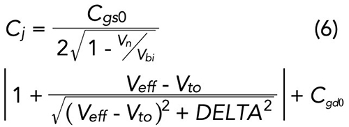
Unfortunately, no single equation relates the diode capacitance to the diode voltage for the S-curve shape. Instead, to model this behavior, an old FET model known as “Triquint’s Own Model” (TOM)3 is considered. Though initially developed to model three-terminal metal-semiconductor field-effect transistors (MESFETs), the TOM model contains provisions that can accurately describe the S-curve profile of a diode created by shorting the drain and source in a pHEMT FET. Details concerning the TOM model can be found in the paper by McCamant et al.,3 but in summary, the pertinent results are shown in Equations 2 to 6:


Where:
Cgd0 = zero-bias gate-to-drain capacitance
Cgs0 = zero-bias gate-to-source capacitance
DELTA1 = capacitance saturation transition voltage (1/α)
DELTA2 = capacitance threshold transition voltage
Fc = forward-bias depletion capacitance coefficient
Vbi = gate diode built-in potential
Vd = voltage across the diode
*Veff = calculated effective voltage
*Vmax = calculated gate diode capacitance limiting voltage
*Vn = minimum of Vnew and Vmax
*Vnew = calculated new voltage
Vto = threshold voltage
The parameters in the list marked with an asterisk are generated by intermediate calculations and are not part of the final TOM parameter set. Also, note that parameter DELTA1 is sometimes implemented as the reciprocal of another parameter, α, in the TOM model definition.

