WiMAX is a technology for fixed, nomadic and mobile applications that promises the delivery of broadband wireless access to the masses. For fixed and portable access applications, a delivery capacity of 40 Mbps per channel can be expected for typical cells with a radius of 3 to 10 km. Mobile network deployments are expected to provide up to 15 Mbps of capacity within a typical cell diameter of up to 3 km. There are conceptually three ways to achieve this high data throughput in mobile radio communication systems: large bandwidth, higher order modulation schemes and multiple antenna systems, referred to as multiple-input, multiple-output (MIMO). WiMAX deploys all three, each requiring dedicated testing. Also, to optimize the efficiency in terms of time and frequency resources and to enable flexibility for the network operator, WiMAX uses orthogonal frequency division multiple access (OFDMA) as the modulation scheme. This article explains the three techniques for achieving high data throughput and focuses on their impact on test and measurement requirements.
Large Bandwidth Systems
Larger bandwidths increase the data throughput because higher modulation frequencies enable more symbols (a symbol being the smallest unit of data transmitted at one time) to be transmitted per unit time. In other words, a large bandwidth results in a short symbol duration. This can be critical in multi-path fading environments where a signal travels from the transmitter to the receiver along different scattered paths and possibly a direct line of sight path. Therefore, a receiver experiences a superposition of the same signal with different attenuations, phases and delays. The delay spread of the paths depends very much on the physical environment. Indoors, for example, the signals travel similar distances resulting in a smaller delay spread than in the countryside where the difference between the distances a signal travels can be large. Due to the delay spread, different symbols arrive at the same time making it hard for the receiver to distinguish between them, especially if the delay spread is large compared to the symbol duration. This effect is referred to as inter-symbol interference.

The orthogonal frequency division multiplexing (OFDM) transmission technique used by WiMAX has advantages in such fading environments because OFDM signals fill the bandwidth with a series of sub-carriers that individually have smaller bandwidths. This results in a longer symbol duration making the signal less susceptible to fading effects. WiMAX supports different bandwidths from 1.25 to 28 MHz and different numbers of sub-carriers, according to the system requirement and spectrum availability. The number of used sub-carriers can vary between 256, 512, 1024 and 2048. Furthermore, OFDM allows the symbol duration to be increased with redundant information by employing cyclic prefixes—the last part of a symbol is repeated at its beginning. To adapt to different fading environments, WiMAX permits this cyclic prefix to be 1/4, 1/8, 1/16 or 1/32 of the symbol length. The drawback of a long cyclic prefix is a reduction in data throughput. Also, the large bandwidth of WiMAX makes the system susceptible to multi-path fading effects. How efficiently a receiver demodulates a signal under fading conditions can most easily be tested with signal generators that generate standard conforming signals and have an internal fading simulator. The large bandwidth of WiMAX also requires special testing of the transceiver components. For example, in a transmitter, a low frequency or I/Q signal from the baseband chip modulates an RF carrier, which is then amplified. For optimizing the transmitter, it is necessary to distinguish the performances of the baseband chip, I/Q modulator and amplifier. Therefore, modern signal generators and analyzers have to be utilized, not only to generate, demodulate and analyze broadband RF signals, but also the corresponding baseband signals. The large bandwidth of WiMAX signals is a challenge for power amplifier and I/Q modulators. These components are typically tested by feeding a high purity signal to the component and analyzing the output signal to measure the deterioration of the signal caused by the component under test. The in-band deterioration is typically measured in terms of spectral flatness and flatness difference, which is the difference in level between adjacent sub-carriers. The modulated OFDM sub-carriers add up to an RF signal with a high dynamic range. This is typically quantified as the difference between peak and average power and referred to as the crest factor. WiMAX signals have high crest factors of the order of 12 dB. To avoid modulation errors, the power amplifier must be linear throughout such dynamic ranges. To test how an amplifier behaves for signals with different signal characteristics, tools are available to set the crest factor of a WiMAX signal generated by a signal generator. The out-of-band deterioration is measured in terms of the adjacent channel leakage ratio (ACLR). The ACLR gives the power that leaks into the adjacent channel with respect to the in-band power. Such tests of components require signal generators and analyzers with an ACLR and frequency response that is much better than the deterioration due to the component under test.

High Order Modulation
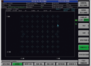
In a digitally modulated OFDM system like WiMAX, an in-phase (I) and a quadrature phase (Q) signal are modulated to each of the radio frequency sub-carriers. The I and Q signals are conveniently visualized in a constellation diagram where I is plotted versus Q. Figure 1 shows such a diagram measured with a signal analyzer. In this figure, there are constellation points, which are discrete I and Q values. During a symbol time one of these I/Q pairs is transmitted per sub-carrier. To each constellation point a bit or a bit sequence is mapped. The different WiMAX modulation schemes, BPSK, QPSK, 16QAM and 64QAM, have 2, 4, 16 and 64 constellation points each corresponding to 1, 2, 3 and 4 bits, respectively. Therefore, the more constellation points, the higher the order of the modulation, the more bits are transmitted per symbol. This means that the data rate is increased without increasing the bandwidth. The price of such higher order modulations is that the constellation points move closer together, making it harder for the receiver to distinguish the points and thus demodulate the signal correctly. This is especially true for low signal-to-noise ratios, in the presence of interference and multi-path fading. WiMAX then adapts the order of the modulation and the coding according to the overall transmission conditions. To test how a WiMAX receiver can demodulate signals in the real world, the operator needs to generate a standard conforming signal and simulate noise, fading conditions and interference. This is conveniently done by signal generators with an internal noise generator, fading simulator and a second baseband source to simulate interference. To cope with the complication of high order modulation, the transmitter and receiver need to have good modulation accuracy, which is typically measured in terms of error vector magnitude (EVM). The EVM equals the distance between the actual measured and the ideal constellation point in the I/Q diagram, normalized to the magnitude of the ideal constellation point. Signal analyzers with WiMAX functionalities facilitate the measurement of the transmitter’s EVM. The EVM can be measured for the individual subscriber, time slots or sub-carrier. To estimate the accuracy, with which a transmitter can generate a signal and a receiver demodulate it, requires a signal analyzer and a signal generator with an EVM much lower than the device under test. When designing transmitters and receivers with a low EVM, care must be taken with regards to some critical performance parameters, which require dedicated testing. In particular, the local oscillator that does the up- or down-conversion must be pure in terms of phase noise and broadband noise. Phase noise and broadband noise have a detrimental effect on the EVM because they lead to azimuthal and radial smearing of the constellation points, respectively. Also, the I/Q-modulator has to map the I and Q signals precisely at 90° with respect to each other and with a linear amplification in order to avoid distortions of the constellation diagram, resulting in an increased EVM.

MIMO
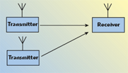
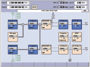
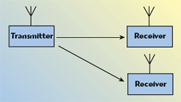
WiMAX, like other modern radio communication standards such as 802.11n and E-UTRA, employs multiple antenna systems referred to as MIMO or spatial diversity. The technique either increases the signal-to-noise ratio or increases the data throughput for a given resource or both. Transmit diversity refers to a system where different signals are transmitted from different antennas at the same time and frequency. Figure 2 shows a schematic of such a system where the signals experience different multi-path fading. The characteristics of these fading channels are estimated by transmitting a known pattern and, with this channel estimation, the receiver can then distinguish between the signals from the transmit antennas. This requires the fading channels to be sufficiently different or uncorrelated. However, the antennas of a transceiver are bound to a limited physical area and residual cross talk between these antennas cannot be avoided. Due to this, the fading channels are actually correlated in amplitude and phase, deteriorating the performance of such a transmit diversity system. In the absence of multi-path fading or for 100 percent correlated fading channels, transmit diversity does not work. This means that the performance of a receiver for transmit diversity systems can only be evaluated with fading simulators that can simulate more than one fading channel and allow complex correlation factors between the paths of the fading channels. Such receivers are tested most effectively with a signal generator containing two baseband generators, which can generate standard conforming signals as they are transmitted from the two antennas, plus two internal fading simulators to simulate the different correlated fading channels. Such equipment means that a receiver in a transmit diversity system can be tested using only one box and with minimum cabling effort. Figure 3 shows the block diagram of a signal generator configured for transmit diversity where the signals from the antennas are generated in the top and bottom blocks on the left; the two signals are then faded in the next two blocks and then routed together and modulated to the RF carrier in the two blocks on the top right. This concept also applies to receive diversity systems, where a signal is transmitted from one antenna and received by two. Figure 4 illustrates such a receive diversity system schematically. Performance measurements on receivers in receive diversity systems require one baseband signal, simulation of two correlated fading channels and radio frequency signals. Figure 5 shows the block diagram of a signal generator set up for testing receive diversity systems.

OFDMA Systems
An OFDMA system is a combination of frequency division duplex (FDD) and time division duplex (TDD). This means that a part of the spectrum and time is allocated to each subscriber. In such a system, operators can offer different bandwidths and transmission time resources to the users according to their needs and level of service. In Figure 6, a time plan for a downlink signal is shown, where, on the x- and y-axes, the time and sub-channel numbers are plotted, respectively. The logical sub-channels are allocated to the physical sub-carrier according to defined permutation algorithms. The orange square in the figure represents the downlink-map or DL-Map. In this field, the time and sub-channel allocation of the users is described. To enable different base stations to operate in the same physical area, different times and sub-channels can be allocated to them. As can be seen, OFDMA systems offer a great deal of flexibility in optimizing resources efficiently. However, this flexibility comes at the price of a complex physical layer with many free parameters. This complexity is a challenge for the user interface of test and measurement equipment as many parameters need to be set and the impact of the parameter must be illustrated to the user (in the form of graphical displays and concise tables, for example). Also, the high complexity of the physical layer presents the risk that manufacturers of transceivers will run into configuration problems. Emulating transmitters and receivers with signal generators and signal analyzers with flexible parameters helps to solve such configuration problems. These tests require the measurement equipment to make fast and easy changes to the WiMAX parameters. Such equipment has proved to be very useful during interoperability testing between subscribers and base stations—by using a signal analyzer, the contents of the DL-Map and UL-Map can automatically be demodulated down to the bit level. This allows the bits demodulated by the signal analyzer to be compared with the ones demodulated by the mobile station. During troubleshooting of an interoperability test, this is one of the first steps that needs to be taken, as the subscriber station needs to demodulate the DL-Map in order to know what sub-carriers to demodulate and when. Once the DL-Map is demodulated correctly, the next logical step is to verify the contents of the UL-Map, which tells each subscriber station how to configure its transmitter in terms of what sub-carriers to use and when to do so. Only if the mobile station transmits its information at the requested sub-carriers with the correct timing, will the base station be able to demodulate the signal correctly. This highlights that timing is a parameter that may cause interoperability problems. Here, a signal analyzer can speed up the troubleshooting process, as it is able to record and display the signal in both link directions.

Conclusion
Large bandwidth signals are susceptible to fading effects. To cope with this, WiMAX deploys the robust OFDM modulation technique. The downside being that the signals have a high crest factor, requiring very linear power amplifiers. Furthermore, the large bandwidth requires power amplifiers and I/Q modulators with a flat frequency response. Transmitting signals with a high order of modulation requires very good modulation accuracy and a receiver that is able to distinguish between the constellation points even in the presence of noise, fading conditions and interference. Besides the generation of multiple signals, the receiver tests for multiple antenna systems require the simulation of multiple fading channels. The flexibility of an OFDMA system also comes at the price of a complex physical layer, which makes interoperability tests a challenge. Therefore, the testing of WiMAX equipment requires high end, easy to use test and measurement equipment to generate and analyze standard conform signals and to simulate interference effects.
Jan E. Prochnow studied physics at the University of Technology, Aachen, Germany, and received his PhD degree in the field of accelerator physics at CERN, Geneva, Switzerland. He has been a product manager for signal generator and power meters at Rohde & Schwarz headquarters in Munich, Germany, since 2004. His tasks include the marketing of test and measurement equipment for WiMAX.
