

This article addresses the requirements of satellite communications (satcom) and space applications. It describes RF transmitters and receivers, along with their block diagrams, which form the basis for many RF systems. It discusses RF components and the attributes of these components in the RF signal chain. Finally, the article explores some of the details of space-based satellite networks and how these requirements influence the trade-offs in the RF components selection process.
THE RF TRANSMITTER AND RECEIVER
A communications network is a sophisticated system that performs many digital and analog functions. Even though most communications networks are now classified as “digital,” signal transmission from the point of origin to the intended target uses analog RF signals. The RF portion of this network contains transmitter and receiver circuitry. In the transmitter, a digital signal carrying the information to be transmitted is converted to an analog signal using a digital-to-analog converter (DAC). This intermediate frequency (IF) signal is conditioned with amplification and filtering before it is converted to a higher RF frequency for transmission. The up-conversion process involves a mixer and a local oscillator (LO) signal from some type of source. A mixer is a non-linear three-port device that produces output signals that are harmonically related to the input signals, along with the sum and difference of these inputs. Proper selection of the input IF and LO signals will produce the desired RF output signal frequency. Once the desired RF frequency range is attained, the signal may undergo several stages of filtering and amplification to remove unwanted products from the mixing process and increase the RF signal power to the appropriate level for transmission from the antenna. This architecture is known as superheterodyne and some of the key RF components in the transmit RF signal chain are the power amplifier (PA), distributed amplifier, filters, voltage-controlled oscillator (VCO) or voltage-controlled SAW oscillator (VCSO), phase-frequency detectors and pre-scalers. An example of this transmitter architecture is shown in Figure 1.
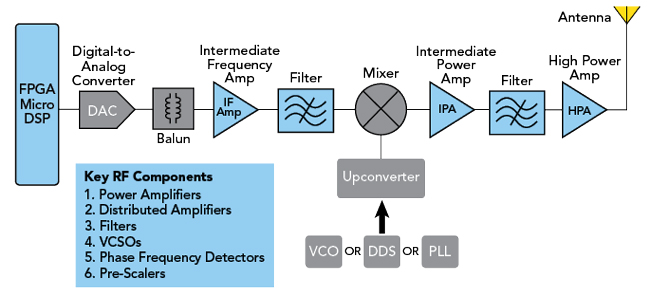
Figure 1 RF superheterodyne transmitter.
The superheterodyne receiver has a similar architecture, but it serves a much different purpose. At the receiver antenna, the signal level is likely to be very low. The first order of business is to retrieve the incoming information. This typically involves filtering to remove any unwanted frequency components and then amplify the remaining frequency components to useful signal levels. The first amplification stage is known as a low noise amplifier (LNA) and as the name implies, the purpose of this amplification stage is to add as little additional noise to the input signal as possible. From here, the amplified signal reaches the mixer in the superheterodyne receiver. In this case, the mixer products are chosen to down-convert the input signal to a lower IF frequency for processing. The down-converted signal is filtered to remove unwanted mixing products and then amplified to the appropriate level for processing. An analog-to-digital converter (ADC) converts the analog signal to a digital signal to be processed by a field programmable gate array (FPGA) or a digital signal processor (DSP) in the digital section of the communications network. An example of this receiver architecture is shown in Figure 2.
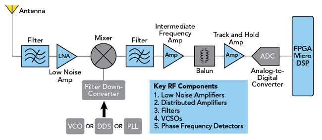
Figure 2 RF superheterodyne receiver.
RF COMPONENTS CONSIDERATIONS
Designing an RF transmitter and receiver chain involves evaluating component trade-offs to find the solution that best satisfies the system requirements. Table 1 shows some of the most important elements of the transmitter and receiver. The PA in the transmitter amplifies the input signal to the appropriate RF output power level for transmission. This signal must also meet linearity requirements, which have gotten more stringent as data traffic increases. The linearity performance is characterized by output third order intercept point (OIP3) and 1 dB compression point (P1dB). Higher OIP3 and P1dB values imply higher PA linearity, which increases spectral efficiency and the ability to keep pace with increasing data traffic requirements. PAs dominate the overall power consumption of the RF signal chain. In addition to creating heat dissipation challenges for designers, this power dissipation translates into operating expenses for providers and general environmental concerns. Power-added efficiency (PAE) is the metric for how efficient a PA is at generating the required output power and amplifier designers are working hard to incorporate new amplifier designs and device technologies to increase PAE.
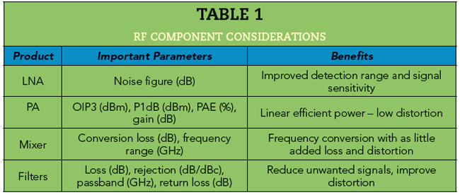
In the receiver, the noise figure of the LNA determines the sensitivity of the receiver. Lower noise figures imply better signal sensitivity and improved detection range. In both the transmit and receive chains, the mixer function converts the RF signal. The conversion loss during this process is an important consideration because more loss in the mixer requires more gain in the amplifier chain to reach the desired RF output power and this may increase cost and power consumption. This is a non-linear device, so minimizing the out-of-band mixing products reduces the requirements on the filters and improves system linearity. The transmit and receive chains both rely heavily on filters of several types and configurations to remove the unwanted signals that all the active elements will generate. Some attributes of important components are shown in Table 1.
For all applications, component reliability is of paramount importance. Reliability is viewed as a “must-have” for the commercial supply chain. The defense supply chain institutes specifications like MIL-HDBK-217 and MIL-STF-883 and space applications may fall under specifications like NASA EEE-INST-002 that address mission length and mission criticality.
Packaging is also a consideration for components. For cost considerations, most low-power components are packaged in plastic. As power dissipation or performance requirements increase, packaging shifts toward ceramics, metal inserts and finally to metal. Space-based applications also must address radiation requirements as designers consider component and packaging design.
SATCOM
Space has become a dynamic market opportunity. Geosynchronous orbit (GEO) satellites orbit 35,800 km away from the Earth with the advantage that these satellites appear stationary to an observer on the ground. High throughput satellites (HTS) in this orbit use phased array techniques with superheterodyne transceivers to provide high-capacity spot beam coverage to users on the ground, along with providing connectivity to airborne and maritime applications.
In what is being referred to as “New Space,” satellites in low earth orbit (LEO) are positioned less than 2000 km above the Earth’s surface. The satellites move with respect to an observer on the ground, so beam tracking and handover on the ground and in space have become important, but satellite constellations launched into LEO orbit are seeing fast growth. These satellites are smaller and less sophisticated than GEO satellites, but as an example of this dramatic growth, Starlink is reported to have 4800 operational satellites in LEO orbit with regulatory approval for a total of 12,000 satellites. These LEO satellites provide connectivity to underserved areas.
The space segment with GEO and LEO, along with a variety of other orbits, has become an essential piece of the global connectivity and national sovereignty puzzle. Data gateways on the ground connect commercial and defense users to the satellite constellation. An emerging segment in the satellite market is “direct-to-device” applications that allow user terminals and handsets to connect directly to a satellite. While these are still low data rate connections, this is a new opportunity. All of these applications and opportunities rely on RF chains similar to those shown in Figure 1 and Figure 2. A conceptual representation of the satellite network is shown in Figure 3.
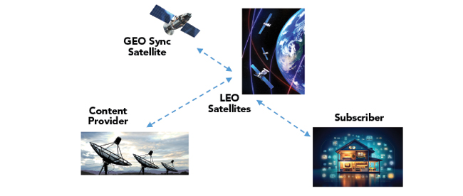
Figure 3 Satellite communication network.
SATCOM FREQUENCY BANDS
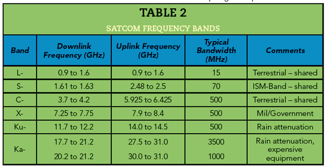
Satcom frequency bands are shown in Table 2. Earth stations transmit the uplink signals to a satellite at a higher operating frequency, while satellites transmit at a lower operating frequency to be cost-effective. As we go to higher frequency bands, such as Ku- and Ka-Bands, there is more bandwidth available resulting in higher data rates. There are challenges with these 12 to 40 GHz frequencies; there is attenuation due to rain and the signal propagation characteristics of mmWave transmission. In addition, higher frequencies mean the equipment needed to transmit and receive the signals becomes more expensive equipment.
SATELLITE ORBITS
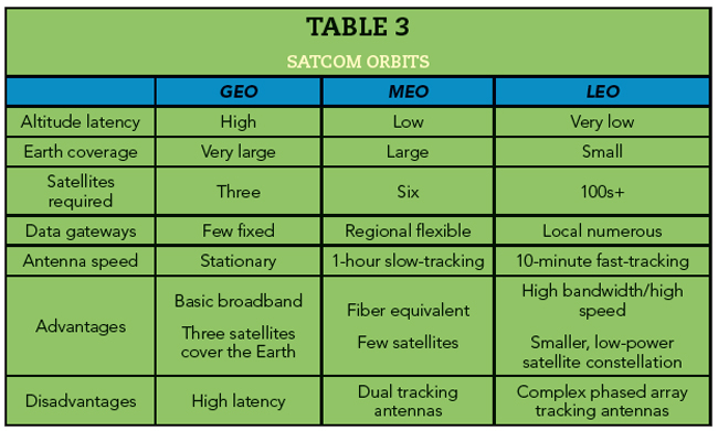
In addition to LEO and GEO orbits, medium earth orbit (MEO) is another popular orbit for satellite constellations. This orbit, ranging from 2000 to 35,800 km, fills the gap between LEO and GEO. All these orbital planes offer advantages and disadvantages.
Satellites in GEO have high latency because of the distance from the Earth, but each satellite can cover a very large footprint. Three GEO satellites have sufficiently large footprints to cover essentially the entire globe, missing only the polar regions. Since MEO satellites are closer to the Earth, they have less latency. However, six MEO satellites are typically required for coverage like GEO satellites. As mentioned, GEO satellites appear stationary to a point on Earth. As orbit gets closer to Earth, satellites begin to move with respect to that point. MEO satellites require a slow-tracking antenna. LEO satellites are closest to Earth and have the lowest latency but each satellite only covers a small area. LEO constellations require hundreds or thousands of satellites to provide coverage and they require a fast-tracking phased array antenna. LEO satellites have become attractive because they are smaller, less sophisticated and lower power, making them less expensive to manufacture and launch. A summary of these attributes is shown in Table 3.
SATCOM RF SIGNAL CHAIN
Table 2 shows that satcom links use frequency-division duplex (FDD), meaning uplink and downlink communication happens in different frequency bands. This is done to enable bidirectional data transfer and minimize channel interference. The uplink (Earth station to satellite) band is higher in frequency than the downlink from the satellite to minimize the cost of the satellite electronics. Figure 4 shows a more detailed block diagram of a representative satellite RF signal chain. The receive and transmit architectures, along with the functionality, are like what was described earlier.
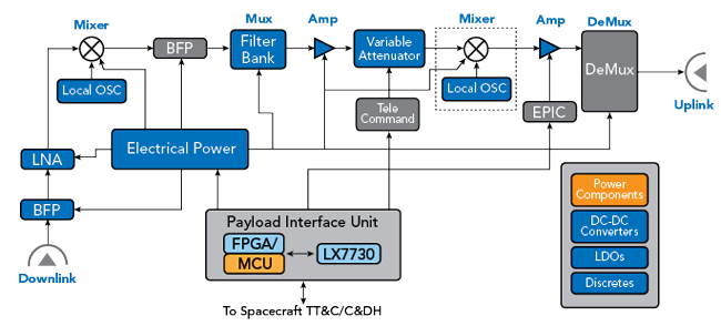
Figure 4 Satcom RF signal chain.
There are some differences. The satellite downlink signal received at the ground terminal first encounters a bandpass filter or a diplexer. In this application, the incoming signal is so low, it is best to filter out any unwanted components before amplification. The block diagram in Figure 4 shows filter banks that would contain switches, along with multiplex (Mux) and demultiplex (Demux) functions that reflect channelization in the satellite signal. An important point is that while architectures for communication applications may have different realizations, the principles are the same.
COMPONENT SELECTION FOR SPACE
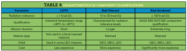
The emergence of the commercial space industry with private launch companies, small satellite constellations and sub-orbital tourism, along with other efforts to reinvent the traditional space industry, has created a different component design and selection mindset. With shorter missions, component selection requires cost-effectively meeting the mission goals. Component qualification requirements can vary by function, from commercial off-the-shelf (COTS) to radiation-tolerant to radiation-hardened depending on the space environment and exposure. GaN-on-SiC and GaAs components can be screened for radiation-tolerant or radiation-hardened requirements. COTS components typically have an industrial temperature range, a radiation tolerance under 1 krad (Si) and are less expensive. Radiation-tolerant components can be characterized by radiation tolerance levels from 15 to 50 krad (Si) and have higher costs. Radiation-hardened components have radiation tolerance over 100 krad (Si) and are significantly more expensive. Some of the relative performance considerations for these categories are shown in Table 4.
POWER AMPLIFIERS REQUIREMENTS
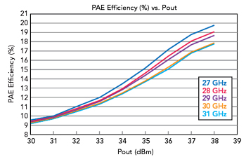
Figure 5 ICP2840 PAE for various frequencies.
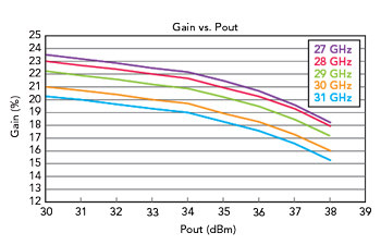
Figure 6 ICP2840 gain for various frequencies.
PAs are fundamental in the RF signal chain. With the need to increase data rates and capacity, linear PA operation to minimize RF distortion is becoming essential. Satcom systems that use higher-order modulation schemes, such as 64-, 128- and 256-QAM, are extremely sensitive to non-linear behavior. Another challenge is achieving acceptable peak-to-average power ratios (PAPR). PAPR or the ratio of the highest power the PA will produce to its average power determines how much data can be sent and this metric is proportional to the average power. At the same time, the size of the PA needed for a given format depends on the peak power. 5G mmWave EIRP requirements mandated by the FCC include 43 dBm EIRP transmit power for the mobile handsets and base station transportable power of 55 dBm EIRP. These and other conflicting challenges can be met with GaN-on-SiC PAs for satcom, 5G, aerospace and defense applications.
POWER AMPLIFIER TECHNOLOGIES
GaN-on-SiC has a high power density, allowing amplifiers using this technology to generate highly linear output power with high efficiency. GaN-on-SiC PAs can operate at frequencies in the Ka- and Ku-Bands ranging from 12 to 40 GHz with broad bandwidths for commercial and defense satcom and 5G applications. In addition to the frequency characteristics, GaN devices exhibit high gain and better thermal properties than other technologies allowing this technology to be used for a wide range of RF applications. The PAE for a Microchip GaN amplifier is shown in Figure 5. Figure 6 shows the gain characteristics for this same device.
CONCLUSION
The space market is thriving as satellite constellations fill a valuable role in the vision of global high speed connectivity. Traditional satellites in GEO are evolving to provide high data rate connectivity and large numbers of satellites in LEO constellations have started to expand connectivity options. The transmitter and receiver architectures for these and other wireless and wired communications networks are very similar. This article has presented these architectures, along with some of the important trade-offs and selection criteria for these space-based applications.