Wireless technology is essential for defense, enabling everything from radar and radio communications to drones and navigation. With these requirements growing, more capabilities must be integrated into less hardware and antennas are becoming a bottleneck. Specialization in antenna subsystems results in multifunction wireless systems requiring multiple conventional antenna systems. This is not feasible for platforms with stringent cost, size, weight and power (C-SWaP) constraints. This article proposes gradient index (GRIN) lenses as an antenna solution that integrates multiple features into a single aperture, dramatically reducing C-SWaP.
The sheer variety of defense wireless applications and the breadth of operating frequencies have spurred the adoption of dedicated antenna systems. Large naval vessels are studded with reflectors and arrays with each system performing unique sensing duties. Other craft are likewise dotted with myriad dipoles, slots and reflectors that serve different purposes in different bands. This approach has to evolve as the nature of battlefield electromagnetic superiority is rapidly changing. The core of wireless spectrum dominance is moving from aircraft, ships and bases to the frontline. At the tactical edge, small platforms reign. Ground vehicles, small UAVs and personnel are increasingly involved in wireless operations. One-way drones and active decoys, which protect higher value assets, are increasingly common. These small platforms have stringent C-SWaP constraints so they cannot carry heavy, conspicuous antenna systems. Their deployment scale makes it economically infeasible to encumber these units with active electronically scanned arrays (AESAs).
Developing low C-SWaP multifunction apertures is complicated because the antenna must support three advanced radio features: low probability of detection (LPD), spatial selectivity and multi-band operation.
LPD refers to specific waveforms and modulation schemes that obfuscate the actual signal. While these signal-level features are essential, an additional layer of LPD can be achieved with high directivity antennas since a narrow beamwidth lowers the risk of unintended detection. High directivity also improves jamming resilience because signals outside the beam are attenuated.
High antenna directivity enables spatial selectivity and increases range. From a sensing perspective, these features provide more detailed spectrum reconnaissance, along with enhanced survivability in the presence of hostile radar. Given the highly mobile nature of small platforms, the antenna system must electronically control beam direction over some field of view (FoV). This can be achieved with an AESA.
Classical AESAs are generally neither cost-effective nor power-efficient, particularly when operating over an extremely wide bandwidth. For wideband operation, an AESA generally requires extremely wideband beamforming chipsets and antenna elements, components that are expensive and difficult to procure. Complex AESAs are typically developed in-house for specific applications and wideband variants and this is not an ideal cost basis for widescale adoption on small platforms.
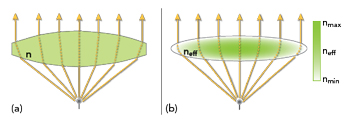
Figure 1 (a) Homogeneous lens antenna. (b) GRIN lens.
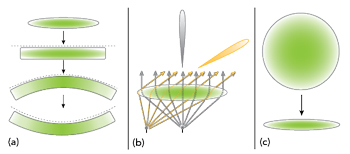
Figure 2 (a) Arbitrary geometry GRIN lenses. (b) Wide-angle beam-scanning GRIN lens. (c) Thin, lightweight GRIN lenses.
GRIN lens technology is well-suited to these requirements. GRIN lens antennas have shown directivity greater than 30 dBi,1 which aids in LPD. They also achieve high FoV beam scanning without beam squint for spatial selectivity.2 Most GRIN devices are true time delay, enabling extremely wide instantaneous operating bandwidths for multifunction apertures.3 Having these features available in a single aperture makes GRIN extremely attractive for small platforms. GRIN system versatility appeals to applications like fixed wireless access, 5G/6G and satcom. With appropriate materials, GRIN systems are also suitable for high temperature applications like high-power microwaves (HPMs) counter-UAS and even hypersonic radomes.
WHAT IS GRIN?
Microwave lenses are conceptually identical to “conventional” optical lenses. Figure 1a illustrates a lens constructed from a homogeneous dielectric of constant index of refraction (n). The lens, assumed electrically large, collimates rays produced by a low directivity feed antenna, forming a high directivity beam. Rays incident on the lens surface are bent upon entering and exiting the lens according to Snell’s law. Within the lens, rays travel in straight lines. The shape of the lens surface dictates its behavior and the geometry of a homogeneous dielectric lens is constrained by its application.
A more general approach proposed in 1853 and widely attributed to Maxwell, allows the lens material and its index of refraction to vary spatially.4 Figure 1b illustrates this GRIN concept. In a GRIN lens, rays refract throughout the lens, not just at its surface.
This creates important advantages. The shape of a GRIN lens is not constrained by its application. Flat or conformal GRIN designs are possible, as shown in Figure 2a. A GRIN lens can correct aberrations at the focal plane, enabling wide FoV beam scan as shown in Figure 2b.2 GRIN lenses can be more compact and lightweight as shown in Figure 2c.5 Finally, unlike homogeneous lenses, which have an impedance discontinuity at the surfaces, GRIN lenses provide a smooth transition from air to lens dielectrics, maintaining high transmission efficiency over a wide operating bandwidth.
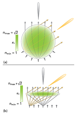
Figure 3 (a) Luneburg lens. (b) Flat GRIN lens.
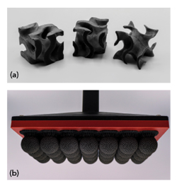
Figure 4 (a) Gyroid unit cell. (b) RF lenses from Fortify Flux Core 3D printer.
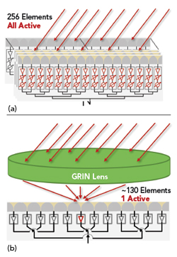
Figure 5 (a) AESA antenna. (b) GRIN lens antenna.
The canonical Luneburg lens, shown in Figure 3a and derived from geometric optics, is the most common GRIN lens. It is spherically symmetrical with an index of refraction varying radially between n=1 at its surface and n=√2 at its center.6 A Luneburg lens has the attractive property that rays emanating from a source on the lens surface are perfectly collimated on the other side. In essence, the Luneburg lens produces a high gain beam for a low directivity feed placed anywhere on its surface. This allows for a theoretically perfect beam scan across an approximately hemispherical aperture by mounting a feed array on its surface. However, Luneburg lenses are bulky and heavy, causing integration issues. The radiating aperture is hemispherical, making it unsuitable for constrained form factor applications, especially where a flush fit to a flat or conformal surface is necessary. The feed array must also follow the lens’ spherical surface, so conventional planar arrays cannot be used.
Alternatively, a flat lens, shown in Figure 3b, can be designed for flat or conformal radiating apertures and focal surfaces. This enhanced design freedom allows for small form factors and integration with planar arrays. However, this freedom comes with two primary challenges that hinder the widespread adoption of flat GRIN components: economically producing high-quality GRIN materials and designing high performance flat GRIN lenses. These are considered in the next section.
ADVANCEMENTS IN GRIN
Understanding why fabrication has been a barrier to flat GRIN lens adoption requires understanding GRIN material manufacturing. Though multiple methods of constructing GRIN exist, the most common approach embeds air structures in a low loss “host material” dielectric. This alters its effective dielectric constant (Dk) and corresponding refractive index.1,2,5 The effective Dk is controlled approximately by the volumetric ratio of air to host material. Dk is lower in regions with more air than host material and vice versa. Achieving the necessary volumetric ratios to produce aggressive Dk gradients is not mechanically straightforward because the air structures must be sub-wavelength. Tooling and tool path capabilities limit machining technologies, making GRIN manufacturing an extensive and expensive process. Standard PCB foundry operations work but these are serial processes with high material costs. Historically, GRIN manufacturing, particularly for high gradient flat lenses, has been prohibitively expensive and time-consuming. However, recent advances in additive manufacturing provide geometric freedom for scalable manufacturing of complicated structures producing GRIN media.
Fortify has developed technology enabling low-cost, high performance GRIN structures. Figure 4a shows a Fortify gyroid unit cell. This cell enables optimized GRIN devices with smooth dielectric gradients.
Fortify’s digital light processing combines parallel manufacturing with high throughput material processing technology to unlock scale production of GRIN media. While competing manufacturing methods like deposition printing, molding or machining are limited to single-unit production, Fortify’s digital manufacturing process duplicates parts at the same manufacturing speed as a single unit. Figure 4b shows 28 RF lenses produced in a single run. Thanks to the flexibility of this process, GRIN media can be produced and optimized without the extra time and setup costs associated with creating tooling and fixtures. These advantages are crucial for integrating GRIN materials into conventional wireless applications and accelerating adoption.
The second challenge for widespread GRIN adoption is the development of sophisticated design techniques for high performance flat lenses. The design freedom associated with flat lenses is immense and no single design heuristic simultaneously guarantees all the multifunction antenna requirements. Only recently have flat lens design techniques advanced to make this possible. Designs proceed iteratively, drawing inspiration from both canonical optics principles and classical microwave circuit techniques.1,2,5
Cheshir Industries’ flat lens design paradigms employ multiple design heuristics simultaneously to achieve wideband, wide FoV, beam scanning flat lenses. GRIN lenses exploit extremely high index gradients to minimize system depth and weight without reducing performance. These designs rely on greater material availability and scalable additive manufacturing to provide superior performance in low C-SWaP applications. Recent improvements in manufacturing and design are making flat GRIN antenna systems economical.
COMPARISONS
Figure 5a shows a conventional AESA antenna. Figure 5b shows a switched-beam GRIN lens system that routs Rx/Tx signals with a single feed and a switch matrix. Switched-beam GRIN lenses are the simplest beam steering architecture and demonstrate three key advantages over conventional AESA systems: they are extremely power-efficient, particularly on receive; beamforming is intrinsically wideband and switched-beam GRIN systems require few electronic components, making them cost-effective.
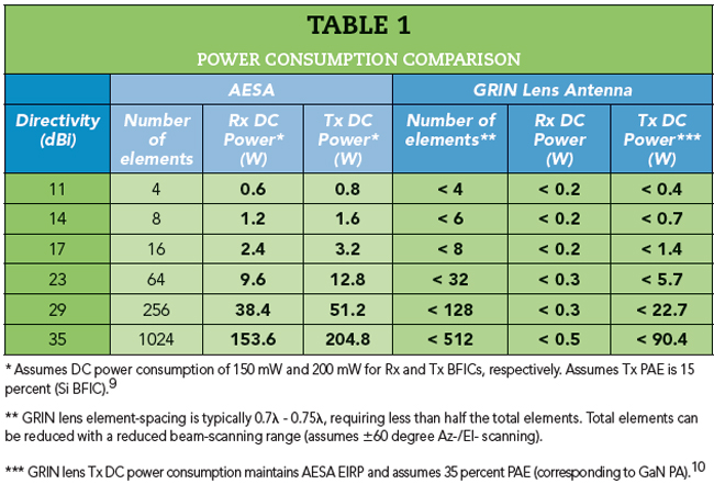
In a switched-beam system, one element generates or receives a beam. A conventional AESA requires every element to be active. A switched-beam GRIN system receiver requires <1 n the total power consumption of a comparable aesa with elements as shown in Table 1, resulting in tremendous power savings.7