

The Tx case is complicated by the EIRP requirements. With a single element transmitting per beam, the switched-beam power amplifier (PA) requires higher saturated power. As a result, a switched-beam system may need GaN or GaAs Tx PAs, whereas the AESA might use a silicon PA. However, this may also be an advantage. The Tx PA dominates the total power of the switched-beam GRIN system and GaN/GaAs PAs can achieve better power-added efficiency values than silicon beamformers.
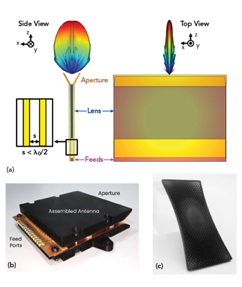
Figure 6 (a) PPWG antenna fan-beam. (b) PPWG GRIN lens demonstrator. (c) PPWG GRIN lens.
Multiband/wideband systems increase these power savings since a single GRIN aperture may replace multiple AESAs. GRIN lenses have demonstrated instantaneous bandwidths of 5:1 and bandwidths greater than 10:1 are possible.1,2,5 Conversely, AESAs typically do not exceed 1.2:1 bandwidth, meaning a wideband system may require multiple AESAs.8
Cost is an important differentiator. Switched-beam GRIN systems produce a comparable FoV with half the elements of AESAs. Switched-beam systems do not exhibit grating lobes and they are not constrained to λ/2 element spacing. Because a single feed element has a 1:1 correspondence with a beam, the system requires only as many feeds as beams necessary to cover a specified footprint. Switched-beam systems do not require VGAs or phase shifters, reducing component count by more than 75 percent.
SWITCHED-BEAM DEMONSTRATOR
Figure 6a shows a 20 to 40 GHz switched-beam flat GRIN lens conceptual prototype system with a 2:1 instantaneous bandwidth. This device comprises a GRIN lens and feed antennas mounted inside two conductive plates that form a parallel plate waveguide (PPWG). Waves collimated by the lens radiate from the flared aperture in a distinctive “fan-beam” pattern.2 Each feed antenna corresponds to a different azimuth beam.
The fully assembled prototype shown in Figure 6b weighs 180 g. The lens is low loss Rogers Radix™ Printable Dielectric material printed with Fortify’s DLP process. Figure 6c shows a sample.
Figure 7a, Figure 7b and Figure 7c show radiation patterns for a 13-beam prototype demonstrating a ±52 degrees FoV. The beams exhibit < 3 dB crossover for 20 to 35 GHz and < 4 dB crossover for 35 to 40 GHz. At 40 GHz, scan loss is below 2 dB for the farthest beam, corresponding roughly to a scan loss envelope of cos0.6 (θ). An “ideal” scan loss envelope of cos1.0 (θ) is shown for comparison.
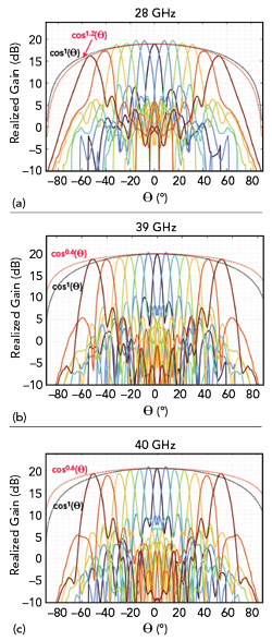
Figure 7 (a) 28 GHz (5G-NR N261). (b) 39 GHz (5G-NR N260). (c) 40 GHz (maximum frequency).

Figure 8 Cylindrical GRIN lens.
DEMONSTRATORS AND PRODUCTS
GRIN lenses can operate from C- to V-Bands. These lenses range from traditional spherical Luneburg to optimized cylindrical, radially symmetric geometries that increase existing antenna system gain. Figure 8 shows a cylindrical lens mounted to a Ka-Band horn antenna. The lens increases gain by 6 dB.
For applications requiring phased array pointing resolution and flexibility, along with a broader FoV and lower scan loss, Fortify and Rogers designed and fabricated a lens capable of increasing phased array FoV from ±60 to ±90 degrees. Reducing antennas is attractive in FWA and satcom-on-the-move applications. Defense organizations are exploring FoV-enhancing lenses for AESAs used in radar, electronic warfare and wireless tactical communications.
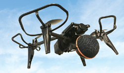
Figure 9 Drone-mounted retroreflector.
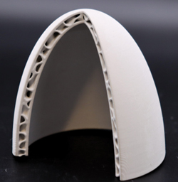
Figure 10 Ceramic radome.
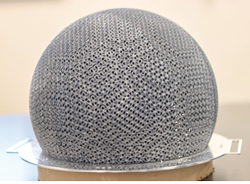
Figure 11 13” diameter Ku-Band GRIN lens.
GRIN lensing is a convenient and powerful way to simultaneously increase antenna performance and reduce mass. Lenses have been produced with competitive performance and approximately 50 percent weight savings. The increased antenna power-to-weight ratio offers advantages in radar cross-section augmentation on UAVs or live-fire target vehicle applications where C-SWaP requirements are stringent. Figure 9 shows a Luneburg lens-enhanced retroreflector mounted to a quadcopter drone.
ADDITIONAL APPLICATIONS
A host of applications can use GRIN capabilities. HPM devices use high-power RF pulses and narrow beams to disable sensitive electronics, often on UAVs. A GRIN lens HPM solution can be substantially more compact than a reflector and the architecture is more amenable to integration with a feed array for beam scanning. Low loss, high power handling 3D-printable ceramics like alumina are also attractive options for this application.11
Ceramic GRIN is suitable for heat-resistant radomes on hypersonic vehicles. Hypersonic vehicles experience very high surface temperatures, making ceramic and ceramic composites compelling materials for vehicle surfaces.12 GRIN radomes can be designed to tune the radiation patterns or enhance the bandwidth of antennas while satisfying thermal requirements. Fortify has designed and manufactured nose cone devices with unique composite sandwich architectures that enable efficient broadband transmittance for high temperature radomes. Figure 10 shows an example.
GRIN lens antennas are a power-efficient alternative to beamforming arrays in 5G FR2 and upcoming 6G FR3 (7 to 20 GHz) bands. The wide instantaneous bandwidth of GRIN apertures could also provide RAN-sharing benefits by addressing multiple frequency bands, simultaneously.13 This configuration could reduce the hardware and cost of high capacity 5G/6G deployments.2 Similarly, GRIN lens antennas could provide a solution for wideband PtP/PtMP FWA. A switched-beam GRIN system forms multiple beams without reducing EIRP, allowing a single access point to address multiple nodes without performance degradation.
GRIN lens antennas offer advantages for satcom systems. For ground applications, a single GRIN system can cover Ku- and Ka-Band. A switched-beam system with multi-beam operation enables make-before-break operation. For the satellite, these features enable high capacity communications to the gateway terminals and users. Figure 11 shows a 13 in. diameter switched-beam satcom lens antenna designed and manufactured by Fortify.
AESA applications provide another opportunity for GRIN lenses. A lens placed over an AESA provides FoV, bandwidth and pattern enhancements and serves as a radome. The system may be designed so the lens is fed only by a subset of the AESA feeds.7 This phased array-fed lens (PAFL) architecture lies somewhere between a phased array and a switched-beam system. Because multiple elements are excited, the per-element power requirements for a PAFL are reduced from a switched-beam system for a given EIRP. However, a beam only uses some AESA elements, making the PAFL approach more power-efficient than the phased array. The PAFL technique exhibits the benefits of both beamforming approaches while mitigating their respective drawbacks.
CONCLUSION
This article presented an overview of the untapped utility of GRIN lenses with a focus on switched-beam antenna systems. Using quasi-optical approaches and sophisticated design techniques, these antennas are capable of wide-angle, high directivity beam scanning over a wide instantaneous bandwidth. These features make the GRIN lens antenna ideal for multifunction operations onboard small platforms. A prototype antenna system having more than ±52 degrees beam scanning capability over a 2:1 bandwidth and less than 2 dB of scan loss was discussed. GRIN technology is scalable and economical and it can provide myriad performance enhancements in additional applications. While GRIN technology is still nascent, it represents a dramatic shift from conventional antenna paradigms that will usher in a new generation of multifunctional antenna systems.
REFERENCES
- N. C. Garcia and J. D. Chisum, “High-Efficiency, Wideband GRIN Lenses With Intrinsically Matched Unit Cells,” IEEE Transactions on Antennas and Propagation, Vol. 68, No. 8, Aug. 2020, pp. 5965–77, Web: https://doi.org/10.1109/TAP.2020.2990289.
- N. C. Garcia and J. D. Chisum, “Compound GRIN Fanbeam Lens Antenna With Wideband Wide-Angle Beam-Scanning,” IEEE Transactions on Antennas and Propagation, Vol. 70, No. 9, Sept. 2022, pp. 7501–12, Web: https://doi.org/10.1109/TAP.2022.3182420.
- W. Wang, et al., “The Systematic Design of Noncommensurate Impedance Matching Tapers for Ultrawideband Gradient-Index Lens Antennas,” IEEE Transactions on Antennas and Propagation, Vol. 70, No. 1, Jan. 2022, pp. 35–45. Web: https://doi.org/10.1109/TAP.2021.3096552.
- “Solutions of Problems (Prob. 3, vol. VIII. p. 188),” The Cambridge and Dublin Mathematical Journal, XI. Macmillan, 1854.
- N. C. Garcia and J. D. Chisum, “Reduced Dimensionality Optimizer for Efficient Design of Wideband Millimeter-Wave 3D Metamaterial GRIN Lenses,” Microwave and Optical Technology Letters, Vol. 63, No. 5, 2021, pp. 1372–76, Web: https://doi.org/10.1002/mop.32755.
- R. K. Luneburg, “Mathematical Theory of Optics,” University of California Press, 1964, Web: https://books.google.com/books?id=-t4bLCrwf60C.
- W. Wang, et al., “Beamforming Phased-Array-Fed Lenses with >0.5λ–Spaced Elements,” IEEE Transactions on Antennas and Propagation, 2023, pp. 1–1, Web: https://doi.org/10.1109/TAP.2023.3240085.
- Alhamed Abdulrahman et al. “64-Element 16-52 GHz Transmit and Receive Phased Arrays for Multiband 5G-NR FR2 Operation.” IEEE Transactions on Microwave Theory and Techniques, Vol. 71, No. 1, Jan. 2023, pp. 360-372. IEEE Xplore, https://doi.org/10.1109/TMTT.2022.3200415.
- Theis, Guilherme et al. “A Design Framework for Beamforming Integrated Circuits Operating at Mm-Wave Frequencies.” IEEE Access, April 2021, pp. 62232-62240. IEEE Xplore, https://doi.org/10.1109/ACCESS.2021.3073987.
- Nakatani, Keigo, et al. “A Ka-band 15 W Output Power >30% PAE GaN MMIC Power Amplifier with Low IMD3 Over 600 MHz Tone Spacing for SATCOM.” Proceedings of the 18th European Microwave Integrated Circuits Conference, Sept. 2023, pp. 1-4. IEEE Xplore, https://doi.org/10.23919/EuMIC58042.2023.10288948.
- “Greater Design Flexibility with Selectively Metallized 3D Printed RF Ceramics,” Fortify, Web: https://3dfortify.com/white_papers/greater-design-flexibility-with-selectively-metallized-3d-printed-rf-ceramics/.
- R. Tandon, et al., “Ultra High Temperature Ceramics for Hypersonic Vehicle Applications,” SAND2006-2925, Sandia National Laboratories, 1 Jan. 2006, https://doi.org/10.2172/887260.
- B. Yin, et al., “Millimeter-Wave Radio Access Network Sharing: A Market-Based Cooperative Bargaining Perspective,” IEEE International Conference on Communications, 2018, pp. 1–6. Web: https://doi.org/10.1109/ICC.2018.8422986.