

This tutorial on OTA testing serves as a quick reference for the conformance testing of 5G mmWave transceivers. The concepts of OTA testing using direct and indirect far-field, i.e., compact antenna test range (CATR), methods and the essential knowledge to perform OTA conformance testing are presented and discussed. A background on antenna basics and antenna arrays essential for choosing an optimum OTA testing system is provided. Mandatory OTA conformance tests of 5G NR transceivers that are required by 3GPP standards are presented and explained.
INTRODUCTION
5G New Radio (NR) is a radio access technology (RAT) developed by the 3rd Generation Partnership Project (3GPP).1 The main goals of this technology include enhanced mobile broadband (eMBB), a downlink data rate of up to 10 Gbps, massive machine-type communication (mMTC) associated with IoT and ultra-reliable low-latency communication (uRLLC). In addition, mmWave 5G NR systems support wide bandwidths up to 400 MHz.
There are many 5G NR frequency bands, from 600 MHz to 52.5 GHz. In the United States, the operating frequencies assigned to 5G systems are designated FR1 and FR2 (FR = frequency range). The FR1 band ranges from 410 MHz to 7.125 GHz and is used to carry most of the traditional cellular mobile communications traffic. The FR2 band (24.25 to 52.6 GHz) is focused on short-range and high data rate capabilities. Additional frequencies have been allocated in the mmWave spectrum from 24 up to 95 GHz. In the United States, three spectrum segments; 28, 37 to 39 and 40 GHz are dedicated to 5G NR. These spectrum segments offer sufficient bandwidth to support the required Gbps data rate transmission.
The integration of the antenna with the RF front end in 5G mmWave devices presents a significant challenge because such devices cannot be connected to the test instruments using conventional coaxial cables. This makes OTA testing2 the only choice to characterize 5G mmWave devices. OTA testing uses antennas instead of cables to connect devices to the test instruments. The OTA test method is mandatory for RF conformance testing of 5G mmWave transceivers operating in the FR2 band.
MmWave signals suffer from severe free-space propagation path loss due to rain, atmospheric absorption and high operating frequencies. They are also susceptible to human, vehicular and foliage blocking, which impacts a receiver’s signal-to-noise ratio (SNR) and degrades receiver throughput. In addition, the propagation effects of mmWave signals limit the link coverage range.
These propagation effects can be mitigated in 5G NR systems by using multiple-input- multiple-output (MIMO) antennas and beamforming techniques. In a beamforming system, narrow directional beams from each antenna element of an antenna array are steered electronically to a specific direction to increase the system’s selectivity. The use of MIMO and beamforming in 5G NR reduces undesired radiated emissions in the direction of other systems, increases coverage range and improves the receiver’s equivalent isotropic sensitivity, which increases the receiver’s throughput.
OTA TEST METHODS FOR 5G NR mmWAVE RADIOS
OTA test systems use antennas to connect a device under test-to-test instruments. Thus, the test antenna is a key element in the test setup and influences the measurements. An antenna is the interface between the guided electrical signal and free space. It transforms the electrical signals from a radio transmitter into electromagnetic waves that propagate in free space and transforms electromagnetic waves into electrical signals for processing in a radio receiver. Antennas are characterized by measuring their radiation patterns in the near- or far-field regions (see Figure 1).3
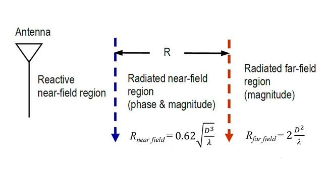
Figure 1 Antenna near and far-field regions.
The boundaries of the near-field region (also called the Fresnel region) and the far-field region (known as the Fraunhofer region) are given by:
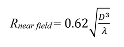
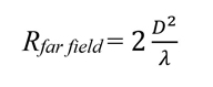
where R is the distance from the antenna to the point of observation, D is the maximum dimension of the antenna in meters, and λ is the free-space wavelength of the propagating signal in meters.
In the far-field region, the propagating spherical wave from the antenna can be approximated by a plane wave (i.e., the phase of the wave is nearly constant). Thus, only the amplitude of the signal must be measured, which simplifies the measurement. Common OTA test methods employ direct and indirect far-field measurement.
Direct Far-Field (DFF) Measurement
In the far-field region of an antenna, the radiated electromagnetic wave from the antenna is considered a plane wave; in this region, the field does not depend on the distance from the antenna. DFF measurements are performed in an anechoic (i.e., without echoes) chamber to prevent any external interference from affecting the measurements. Figure 2a shows an anechoic chamber and Figure 2b shows the spherical coordinate system.
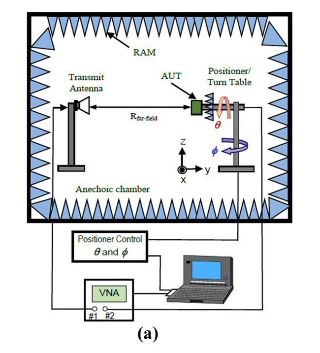
Figure 2a DFF measurement test setup.
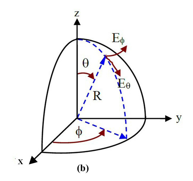
Figure 2b The spherical coordinate system.
In Figure 2a, the pyramidal radiation absorption material (RAM) on the chamber’s walls prevents any reflection from the walls. These walls are made of metal to prevent external interference from entering the chamber. In this test setup, the transmit antenna is used to illuminate the antenna under test (AUT) in the far-field region. The AUT is mounted on a positioner/turntable; the turntable rotates from 0 to 360 degrees (φ angle) in the azimuth plane (i.e., x-y plane). The AUT can also be rotated orthogonally from 0 to 180 degrees (i.e., θ angle).
The positioner and turntable are controlled by a control unit that is connected to a computer placed outside the chamber. In the test setup of Figure 2a, Port-1 of the network analyzer (VNA) is connected to the transmit antenna, and Port-2 is connected to the device under test. The test can also be performed using a signal generator and spectrum analyzer. The DFF method suffers from high propagation path loss at mmWave frequencies. The path loss is given by:
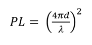
where λ is the signal wavelength, and d is the distance between the transmit and receive antennas.
Although the path loss is high at mmWave frequencies, it can be mitigated with RF amplifiers, but with an increase in system cost. In addition, the required physical space to meet the far-field condition is large. Thus, for 5G NR radios operating in the FR2 band, the DFF test method is not cost-effective. An alternative is the indirect far-field (IFF) method using a CATR.
CATR Description
A CATR4,5 is an IFF measurement method that generates nearly plane waves in a short distance compared to that required for the far-field (i.e., > 2D2/λ). In this method, a horn antenna (referred to as the feed) is located at the focal point of a parabolic reflector that reshapes the field from the horn to a local area providing an ideal uniform phase and amplitude distribution. This area is referred to as the quiet zone (QZ) and is used for performing antenna far-field measurements. Figure 3 shows a CATR and its QZ. The CATR is the most economical option for accurate OTA measurements. It also has much lower path loss than a DFF chamber. Figure 4 shows a practical CATR system.4
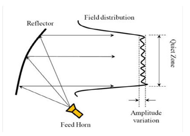
Figure 3 Illustration of a CATR and its QZ.
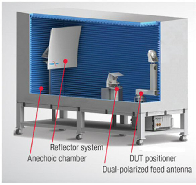
Figure 4 Practical CATR system.4
ANTENNA BASICS AND THE FRIIS EQUATION
In 5G mmWave transceivers, the antenna is integrated with the RF front end and cannot be characterized separately. Thus, the antenna is evaluated by measuring the system’s directive parameters such as the equivalent isotropic sensitivity (ESI), effective isotropic radiated power (EIRP) and error vector magnitude (EVM). Understanding antenna radiation characteristics is essential to interpreting OTA measurement results.
Antenna Radiation Pattern
The radiation pattern of an antenna is a plot of the radiated field/power as a function of the space coordinates at a distance in the far-field. It is usually measured in two orthogonal planes called the E-plane and the H-plane. The E-plane pattern is a measure of the electric field as a function of θ where φ = 0 degrees, while the H-plane is a measure of the electric field as a function of φ where θ = 90 degrees. In the far-field, the electric field E and magnetic field H are perpendicular to one another and the direction of propagation. The E and H fields are related to each other by the free-space characteristic impedance η, which is 120π or 377 Ohms (η = E/H). These planes are related to the antenna’s orientation. Figure 5 shows the far-field radiation parameters of an antenna.
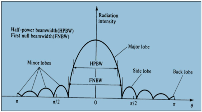
Figure 5 Antenna radiation parameters.
In an ideal antenna, 100 percent of the radiated power is concentrated in the main lobe and no other lobes exist. However, in real antennas, additional lobes (i.e., side lobes and back lobes) exist due to an antenna's manufacturing process and materials. These additional lobes represent unwanted emissions that could interfere with other collocated systems. The radiation pattern provides useful information about an antenna’s radiation parameters. Such parameters include:
- Half-power beamwidth (HPBW), which is defined as the 3 dB beamwidth of the main beam. It indicates how sharp the beam is
- First null beamwidth (FNBW), which indicates the shape of the main beam
- First side-lobe level in dB (relative to the main beam), which is an indication of undesired radiation
- Front-to-back ratio (the peak of the main lobe to the peak of the back lobe), which indicates the directivity of the antenna.
Antenna Gain
Antenna gain is a passive phenomenon; thus, an antenna does not add power but redistributes the power to provide more power in a specific direction. This directed radiated power is more than would be transmitted by an isotropic antenna. An isotropic antenna is a hypothetical antenna that radiates equally in all directions. It cannot be realized in practice, but it is used as a reference for analysis. When the gain of an antenna goes up, the beamwidth becomes narrow, which results in a radiation pattern that is more directive. If a reference isotropic antenna is used for estimating the gain of an antenna, the gain will be expressed in dBi (i.e., decibels relative to isotropic), but if the reference is a dipole antenna (omnidirectional antenna) the gain will be expressed in terms of dBd (decibels relative to dipole, 0 dBd = 2.15 dBi). Figure 6 shows the radiation pattern of an omnidirectional antenna.
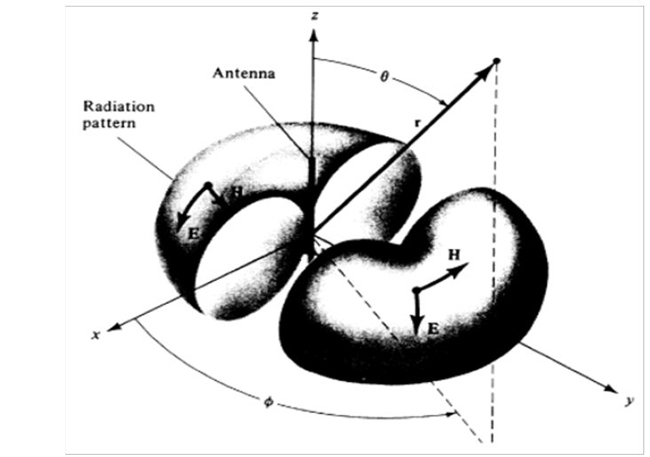
Figure 6 Radiation pattern of an omnidirectional antenna.