

For an isotropic antenna with no loss mechanisms, the input power and the radiated power are the same. However, for a real antenna, there are losses that reduce its radiation efficiency, ηrad. Thus, the antenna gain can be expressed as

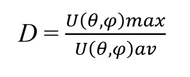
where D is the antenna's directivity. Directivity is a measure of the ability of the antenna to direct radiated energy in a particular direction. Directivity is defined as the ratio of the maximum radiation intensity U(θ,φ)max in a specific direction to the radiation intensity averaged over all directions U(θ,φ)ra, D is given by:
For an isotropic antenna, the average radiation intensity is given by:
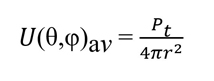
where Pt is total radiated power. For a directive antenna, the radiation density is expressed as:
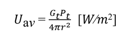
where r is the radius of an imaginary sphere enclosing the radiating antenna, 4πr2 is the cross-sectional area of the sphere at any given distance and Gt is the antenna gain. If the beamwidth of an antenna is known, its directivity can be estimated using the approximate expression:
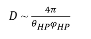
where θHP and ϕHP are the half-power beamwidths at the two principal orthogonal planes.
This equation assumes that the pattern has only one major lobe. The product θHPφHP is referred to as the beam area, also expressed as ΩA where:
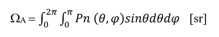
where sr is steradians (1 sr = 1 rad2), and Pn is normalized radiated power.
The beam area ΩA is the solid angle through which the radiated power flows. Antenna gain is often associated with the EIRP, which is the power that would have been radiated by an isotropic antenna to produce peak power density in the direction of maximum gain; thus, EIRP is expressed as:
where Pt is the transmit power. The EIRP is expressed in dBm to simplify calculating the propagation path loss as the ratio of the transmit power to the receive power.
There are several commercial software antenna design tools6-10 that enable calculating the above antenna parameters.
Antenna Efficiency
Antenna efficiency (ηrad) is the ratio of the total radiated power to the antenna's input power and is given by:
where Prad is the radiated power by the antenna, Pin is the transmitter’s output power fed to the antenna’s input and Ploss is the power lost in the antenna due to the antenna materials.
Antenna Aperture and Aperture Efficiency
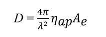
Aperture antennas are antennas that have well-defined aperture areas from which the radiation occurs. Such antennas include reflector antennas, horn antennas and microstrip antenna arrays. Since the field/current on the antenna aperture is not uniform, the effective aperture Ae is less than the physical aperture Ap. Aperture efficiency is expressed as:
The effective aperture is defined as:

The maximum directivity of an antenna is impacted by its aperture’s amplitude and phase characteristics, and it is expressed as:
Antenna Bandwidth
The bandwidth of an antenna is the range of frequencies over which the antenna parameters such as input impedance, gain, directivity, beamwidth and side-lobe levels must meet system specifications.
Antenna Polarization
Antenna polarization describes the orientation of the electric field with respect to the plane of propagation. A receive antenna intercepts only the electric field components that align with its polarization(s). The three commonly used polarizations are linear (vertical and horizontal), elliptical and circular polarization (right hand and left hand). Figure 7a shows a vertically polarized antenna and Figure 7b illustrates the E and H fields of its radiated electromagnetic wave. If the transmitting and receiving antennas have different polarizations, a portion of the signal will be lost; if their polarizations differ by 90 degrees, no signal will be received.
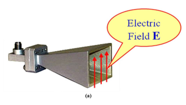
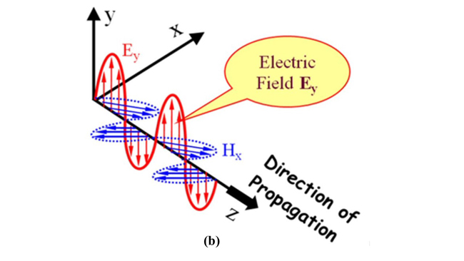
Figure 7 Vertically polarized horn antenna (a) and the E and H fields of its radiated electromagnetic wave (b).
Antenna Input Impedance
Antennas are considered one-port networks and can be described by their S11 parameters (i.e., scattering parameters) or their reflection coefficients (Γ). Knowing Γ, the input impedance of an antenna can be calculated from the following:
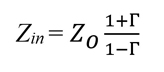
where Zo is the characteristic impedance of the transmission line that is connected to the antenna. The antenna impedance is a complex quantity given by:
where Rant is the resistive part of the antenna impedance, and Xant is the reactive part of the antenna impedance. Impedance matching between the antenna and the RF front end of a radio system should ensure maximum power transfer.
In a radio transmitter, if the antenna is not matched, the transmitter’s output power is reduced and this impacts the communication range. In a radio receiver, if the antenna is not matched, the SNR is reduced resulting in reduced throughput.
Friis Transmission Equation
The Friis transmission equation relates the received power to the transmitted power, where the transmit and receive antennas are separated by a distance r (assuming the receiver is in the far field). The power ratio is expressed as:
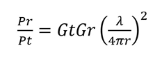
where Gr and Gt are the gains of the transmitting and receiving antennas, respectively, λ is the wavelength of the transmitted signal, and r is the distance between the two antennas.
The received power can be expressed in dBm as:
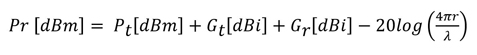
Where the term 20log(4πr/λ) is the propagation path loss in dB. At mmWave frequencies, the propagation path increases relative to microwave frequencies, resulting in reduced power of the received signal and impacting receiver throughput.
ANTENNA ARRAY
An antenna array is a set of antenna elements that are placed in space to form an array with specific characteristics. Such characteristics can be achieved by varying the amplitude and phase of the excitation to individual antenna elements according to the relative position of each element. The total radiated field is determined by vector addition of the fields radiated by each element. The advantages of an antenna array include high gain and directivity, the ability to focus radiated power in a beam in a specific direction and the ability to steer the beam electronically.
Figure 8 is a representation of an n-element microstrip antenna array where θ is the angle of arrival of the radio wave, n is the number of antenna elements and d is the spacing between adjacent elements. For an n-element antenna array with equal spacing between the elements, the total electric field is given by:
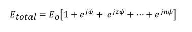
and
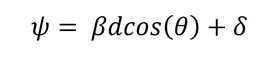
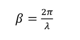
where ψ is the phase difference that is created by the path length difference, δ is the progressive phase shift between the elements (i.e., the phase by which the current in any element leads the current in the preceding element) and Eo is the electric field of the element. From Equation (20), the relative phase between the elements depends on the angle of arrival, the phase of the current in each element, and the spacing between the elements. Equation (19) can be written as:

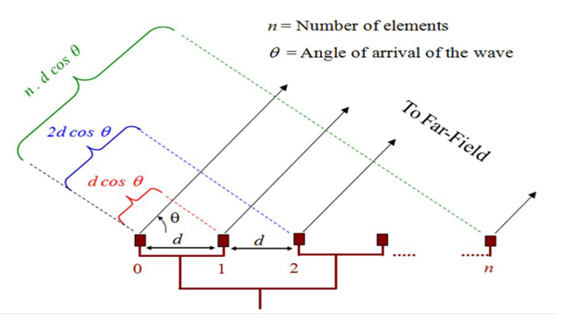
Figure 8 Illustration of an n-element microstrip antenna array.