

In recent years, a surge of new applications, along with legacy applications, are utilizing the mmWave frequencies. This has been enabled by the availability of lower-cost mmWave semiconductors and the advent of active/advanced antenna system (AAS) technologies for communications and sensing that are viable for consumer, commercial and industrial applications. The expansion of mmWave technology and applications is generating new challenges with production tests. Traditional mmWave test methods have been based on labor-intensive manual techniques that require relatively long unit test times. These new applications are creating substantial pressure for modern mmWave production and quality tests to be performed faster and at lower costs. This is causing a shift in the style of interconnect used for testing and the need for greater levels of automation.
INCREASING AVAILABILITY OF MMWAVE TECHNOLOGY
Before the 2000s, the opportunities for mmWave technology were primarily in defense, government or aerospace applications. Some satellite communications (satcom) applications, like satellite television and marine or aerospace communication platforms, used mmWave, but terrestrial wireless communications applications were still in their infancy. During this era, 2G cellular speeds were a fraction of a megabit per second (Mbps).
After the turn of the century, consumer, commercial and industrial wireless communication solutions started gaining traction and automotive radar operating in the 24 GHz band became available. Early mmWave automotive radars still operate in the 24.0 to 24.25 GHz industrial, scientific and medical (ISM) band, which is sometimes referred to as narrowband (NB). The NB automotive radar application is limited in use due to the narrow bandwidth but is still viable for automotive emergency braking and adaptive cruise control. Despite the NB nature of 24 GHz automotive applications, the mmWave spectrum is characterized by wider bandwidth channels and backhaul applications make use of this feature in unlicensed and licensed bands.
Despite several applications, much of this early hardware was manufactured in small batches using manual fabrication, assembly and testing techniques. As the industry exited the 2000s, mass manufacturing of mmWave chipsets and integrated circuits (ICs) started becoming more commonplace. Developments enabled cheaper and more accessible 24 GHz automotive radars that were far less expensive than the previous mmWave technology that, largely, served defense and government satcom applications.
In 2009, the WiGig Alliance introduced WiGig, which was designed to operate in the 60 GHz band. This technology was intended as a wireless standard to replace cable in home theater and wireless docking for mobile device applications. These applications started becoming popular with the advent of the smartphone and 3G. WiGig was subsequently absorbed into the Wi-Fi Alliance and while there were limited launches of WiGig hardware and 60 GHz Wi-Fi routers, the standard did not experience commercial success. Wi-Fi efforts are now directed toward lower frequency IEEE 802.11ax (Wi-Fi 6) and emerging Wi-Fi 7 applications. One of the culprits for this lack of commercial success was likely the higher cost of 60 GHz WiGig chipsets. The high cost of the chipsets discouraged designers from integrating 60 GHz Wi-Fi features into user devices. Figure 1 shows an E-Band radio block diagram and the need for high performance, high frequency, cost-effective RF components is clear.
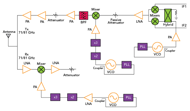
Figure 1 71/81 GHz E-Band radio block diagram. Source: Pasternack.
In the early 2010s, Ku-Band ICs became more readily available and the race toward low earth orbit (LEO) satellite constellations for global broadband began. As Ka-Band satcom networks became more prevalent, investment and interest in Ka-Band satellite constellations and ground terminals for commercial applications increased. During this period, mmWave frequencies emerged as a key enabler for the 5G vision.
The development of phased array antennas and antenna array-related technologies has been a big factor in making mmWave wireless applications attractive for consumer, commercial and industrial applications. These technologies and architectures require more RF paths, but these paths operate at lower RF powers. This approach provides advantages compared to traditional architectures that rely on one high-power mmWave signal path. Lower-power ICs provide the desired result in conjunction with beamforming architectures that utilize antenna drivers. MIMO methods complement beamforming architecture to enable smaller, more compact mmWave antenna systems. This approach also benefits from the smaller physical sizes of mmWave antenna elements.
After 2015, the 3GPP standard adopted mmWave spectrum use and Ka-Band satcom chipsets became more widely available. In addition to wireless mobile communications, fixed-wireless access (FWA) and other satellite broadband applications that make use of mmWave frequencies have emerged. Now, a host of mmWave applications, such as 5G, satcom, Wi-Fi and 77 GHz automotive radar, incorporate mmWave frequencies and components. There is a broad portfolio of applications and use cases that are benefiting from the heavy investment into mmWave chipsets and other technologies. Figure 2 shows a 77 GHz radar block diagram.
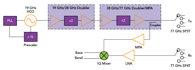
Figure 2 77 GHz automotive radar front-end block diagram. Source: Pasternack.
MMWAVE TRENDS INFLUENCE RF INTERCONNECT
As described, the emergence of mmWave technology in non-government applications is happening quickly. The rapid adoption of mmWave technologies into these applications relies heavily on the development of mmWave chipsets and advances in computing and simulation software. However, the mmWave interconnect ecosystem, which has been in place for decades in response to existing government and satcom requirements, is evolving to meet the needs of these new mmWave applications.
To enable these emerging mmWave applications, interconnect density is increasing, along with operating frequencies. Supporting these trends is necessary to meet the performance requirements of mmWave antenna array applications and AAS systems that have many more signal paths than legacy mmWave systems. As described, the signal paths in these new architectures are at lower power levels than single-path systems. This enables semiconductor technologies, like silicon, GaAs, InP and GaN to provide the required performance.
An important performance consideration in these applications is thermal dissipation. Conduction and dielectric losses are a function of frequency, meaning intrinsic losses in a signal path are much higher for mmWave frequencies. Using multiple signal paths decreases the power and dissipation in each path. This makes it possible to use a distributed thermal management approach in an mmWave system design that accommodates the increased number of signal paths. This approach avoids a high concentration of thermal energy in a small region and minimizes the thermal design challenges.
In addition to an increase in the interconnect volume for devices and systems, mmWave interconnects require better tolerances to ensure proper connection. The operation of a transmission line and the interaction of electromagnetic waves within a transmission medium is a function of frequency. This means that the required surface finish, feature tolerances and size of the transmission lines scale with frequency. At higher frequencies, better finishes, machining and tolerances on coaxial alignment result in the lowest loss and VSWR, along with the best conformability for the coaxial cable assembly.
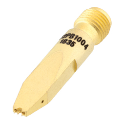
Figure 3 Manual test probe positioner.
Higher frequency interconnects must also have better overall alignment tolerances than lower frequency cables to ensure optimal performance. For instance, the wavelength of a 500 MHz signal is roughly 600 mm, a 50 GHz signal is 6 mm and a 150 GHz signal is 2 mm. As a rule of thumb, it is recommended to keep feature resolution and tolerances below one-tenth of a wavelength and ideally below one-twentieth of the highest operating wavelength. For the 500 MHz feature resolution just described, tolerances should be below 60 mm and ideally, below 30 mm. At 50 GHz, the resolution/tolerances should be below 600 μm and ideally below 300 μm.
Within an RF module and an AAS, it is possible to use planar transmission lines, vias, high frequency mezzanine connectors, solderable coaxial cables and other high-density, board-to-board and cable-to-board interconnects that present a relatively small pitch and profile. However, for test and measurement applications, like prototyping and quality control, the types of interconnects just described are not generally viable. With mmWave technology being used in more and higher volume applications, long, manual processes for prototyping and quality testing do not support the time and cost requirements. The result is a growing use of spring probes (pogo pins), coaxial spring probes and blind mate connectors, as opposed to the legacy standard threaded coaxial connectors and solderable coaxial cable interconnects. Figure 3 shows a manual test probe positioner and ground-signal-ground probe with a 2.92 mm coaxial connector interface that may be used for mmWave test applications.
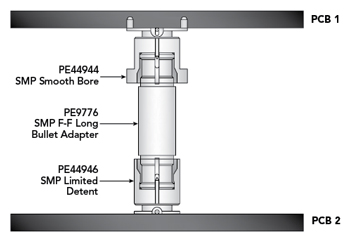
Figure 4 Blind mate coaxial interconnect.
RF port counts are increasing rapidly. Systems that have traditionally incorporated roughly one to four ports are now routinely incorporating 64 or more ports. This increases the urgency of finding smaller, lower-pitch, high performance interconnects for mmWave applications. In many cases, flexible coaxial cable assemblies that are commonly used in test and measurement applications to accommodate various devices under test and test setups are not adequate for mmWave applications. Rigid and semi-rigid coaxial cable assemblies tend to have lower losses and better VSWR than comparable flexible coaxial cables. However, skilled technicians must shape rigid and semi-rigid coaxial cables to properly install these interconnects. Flexible coaxial assemblies only require a technician to push-fit or properly thread and torque a threaded coaxial connector. These assemblies do, however, require some attention to ensure minimal deflection of the flex cable during operation or between calibrations. Rigid and semi-rigid coaxial cable assemblies generally cannot be reworked and should be formed and left in place. Using these cables requires some planning, along with adequate tools and expertise in the laboratory or test floor to properly form and install the connectors. Figure 4 shows a blind mate coaxial connector that uses a bullet adapter to connect between two PCBs.
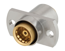
Figure 5 Pasternack BMA connector.
Another solution is to use probes and precision positioners to make RF connections for prototype and verification/quality testing. Using probe interconnects in this way requires planning and design to ensure that there are enough test points for the RF paths. This test setup requires complex probe heads and precision positioning to connect every test point properly and reliably. These tests may require several to thousands of test cycles, depending on the device or system under test. In some cases, it may be necessary to probe multiple sides of a device or system simultaneously. As an example, many transmit-receive modules for AAS applications are fabricated on planar laminates or ceramic boards where the routing may only allow probe test points to be on the top and bottom. This requires dual-sided probing to access all test points and typical probe stations/probe positioners are designed to probe only a single side. This may require a custom probe station or precision probe positioner. Figure 5 shows a blind mate connector operating from DC to 22 GHz that can be used in these applications.
AUTOMATION IS INCREASINGLY CRUCIAL
There is a shift away from high-mix, low volume mmWave devices and systems to much higher volume production. Part of this volume increase has been enabled by greater levels of integration of mmWave technology. Chipsets and ICs with more integrated features are available but there also has been a shift toward more automation and less manual manufacturing, assembly and testing. Automating manufacturing and assembly of RF parts has been an ongoing advancement for decades and automation in this area leverages many of the technologies used for high speed digital and computing systems. However, automation of both prototype and laboratory RF testing and quality/verification testing of mmWave components and systems has lagged other automation implementations that have realized lower costs and higher volumes.
Initial applications have not lent themselves to automating mmWave tests. Government and defense agencies have dominated these applications and they can accommodate the costs and yields of manual and time-consuming mmWave test strategies. Until the recent upticks in volume and cost concerns, there has not been substantial pressure to develop lower-cost, faster and more automated solutions. Additionally, government and defense users may be more willing to sacrifice repeatability and cost in the products to meet stringent standards and performance requirements.
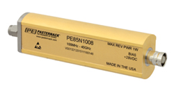
Figure 6 Calibrated noise source module.
Technologies like electronic calibration (e-Cal) have been instrumental in making typical small-signal RF testing more repeatable and reliable. However, these technologies still require interconnect cycling between calibrations. Greater emphasis on the repeatability, accuracy and reliability of mmWave test systems necessitates more automation and less manual effort in moving mmWave devices and systems between calibration and various test setups. Beyond small-signal S-parameter testing, there is also a need for large-signal S-parameters and power, impedance (load-pull) and/or noise testing measurements in many mmWave systems, especially TR modules and other active RF devices and systems. Traditional quality/verification testing of mmWave devices and systems usually involves the use of various test stations or lines. Naturally, having to disconnect, transport and reconnect a device or system under test in a different location, even within the same facility, can result in test variations and changes. Consistency and repeatability concerns resulting from the various test domains of a given device or system under test make harmonizing the results of these test domains difficult, if not impossible. Figure 6 shows a precision-calibrated noise source module with 2.92 mm coaxial connector interfaces that may be part of an mmWave test setup.
Making the test setup flexible enough to perform all the necessary quality/verification tests minimizes data repeatability concerns. It also results in higher test throughput and fewer steps with less manual intervention. As an example, this approach might allow small-signal and large-signal S-parameters for a transmitter module to be measured and the data harmonized without substantial manipulation. This would provide a more complete analysis of the overall transmitter behavior for sensing or communications applications.
Another outcome of additional automation, especially with interconnect, is a dramatic increase in connection repeatability when compared to manual insertion and connection. Though the repeatability of properly torqued threaded coaxial connectors by a skilled technician may be very high, the repeatability of blind mate connectors and other insertion methods is less so. The speed of mating and occupied space advantages of blind mate connections may outweigh repeatability concerns. The optimum solution is to enhance the repeatability of blind mate connections with robotic connection cycling instead of human operators. A robotic insertion system will likely ensure much better repeatability than human operators for spring probes and blind mate connections. The goal would be to achieve the same repeatability as threaded coaxial connectors. Using spring probes and blind mate connectors with automation can also reduce the overall test time and may reduce the test system footprint as robotic systems can be designed that require less area than human operators need. Faster interconnect speeds could result in higher throughput that would lower test costs and increase the ROI of what are becoming increasingly expensive test and measurement systems for emerging high port count mmWave systems.
CONCLUSION
For decades, mmWave technology was relegated to defense, aerospace, space and some backhaul communications applications. To support the insatiable demand for data consumption, along with mitigating spectrum clutter concerns in the sub-6 GHz telecom spectrum, applications are moving to higher frequencies. The advent of mmWave 5G applications has renewed interest in consumer, commercial and industrial mmWave communications and sensing. This interest is being kindled into a roaring flame with many new non-government mmWave applications emerging and evolving. Some of these applications include 5G FR2, 802.11ay from 57 to 64 GHz, automotive radar from 77 to 81 GHz, mmWave imaging/radar for security and machine learning and new space communication and sensing. Each of these new applications needs a robust supply chain of interconnect options and will benefit from more automated manufacturing and testing approaches.