

In induction heating, an electromagnetic (EM) field created by an RF source excites electrical currents in the material that lie within the EM field of the inductor. Because the material will have resistance, these currents heat the object. The amount of heat generated depends on the magnitude of the induced currents, the resistance of the material and the duration of the magnetic field.
In dielectric heating, materials with poor electrical conduction are placed in a varying RF EM field. Typically, these systems will have two metal plates that serve as electrodes and the material between these two plates forms a capacitor. The heat results from electrical losses in the dielectric material forming the capacitor. The advantage of dielectric heating is that the dielectric is uniform, resulting in uniform heating throughout the object. In the specific case of materials containing water, the RF generator creates an alternating electric field between the two electrodes. The polar water molecules in the material will reorient in response to the varying polarity of the electric field and the friction resulting from this molecular movement results in heat. This is the basis for the microwave oven, which was developed just after World War II in 1945.
Given the heritage of industrial RF heating applications and microwave ovens, these early models derived the RF energy required for heating from tube-based sources. Tubes will generate the necessary RF power, but they have disadvantages. The tubes are physically large, meaning single application points for the heating systems. EM wave interference can easily lead to hot and cold spots within the heating chamber as waves interfere constructively and destructively. The tubes typically operate from extremely high voltages and the tube is an emissive technology, meaning that an electron beam is generated from the source and amplified, limiting the lifespan of the tube. As these applications evolve, vacuum tubes are still widely used as power sources, but solid-state solutions are emerging as competitive alternatives.
Solid-state semiconductor devices alleviate many of the issues of vacuum tubes in RF energy applications. The devices themselves are small and voltages can be much lower. This means an RF heating device can have multiple application points within the heating chamber. This provides a much more uniform heating environment. Unlike the tubes, solid-state devices can be set to intermediate output powers and these power levels can change over time and in response to sensor feedback to provide an optimized heating profile. Most importantly, the lifespan of a solid-state source is measured in years and not cycles.
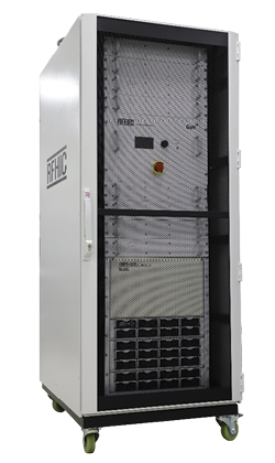
Figure 1 RFHIC RIK0930K-40TG 30 kW system.

Figure 2 Royal Caribbean’s Icon of the Seas.
While consumer-grade microwave ovens remain the most attractive applications because of the volume of the opportunity, less cost-sensitive industrial applications are proving to be early adopters of solid-state technology for RF heating. The performance of GaN devices, particularly power density, in RF heating applications is giving this technology a competitive edge. Solid-state technology, in general and particularly GaN technology, is enabling new RF heating applications and new performance standards in existing RF heating applications.
One of these applications is pyrolysis. Pyrolysis is the process of heating an organic material, typically in the absence of oxygen, to temperatures above the decomposition temperature of the material. At these temperatures, chemical bonds in the molecules of the material will break and the fragments usually become smaller molecules. This is the process used to produce charcoal from wood and it has been in use for quite some time. Ancient Egyptians are believed to have obtained embalming fluid from the pyrolysis of wood.2 New applications of this process and how GaN is enabling these new developments are leading to exciting and innovative opportunities.
Marine vessels, particularly cruise ships, generate a lot of carbon-based waste. A 2022 article in Reuters estimates that a typical cruise ship will generate more than one ton of solid waste every day that it sails.3 With cruising exceeding pre-pandemic levels and new ships getting even larger, this problem will only get worse. While cruise ships are the most obvious example of this issue, it exists in all marine vessels.
THE PATH FORWARD
Vow, a Norwegian company devoted to converting biomass and waste into other resources and alternative energy sources, has partnered with RFHIC through their subsidiary, Scanship. The purpose of this partnership is to develop an innovative, microwave-assisted pyrolysis (MAP) system for waste management. The centerpiece of the pyrolysis system is RFHIC’s 30 kW, GaN solid-state microwave generator system. The RIK0930K-40TG is a full rack-mount system operating from 900 to 930 MHz with eight solid-state power amplifier (SSPA) shelves, a power supply unit, a main control unit and a WR975 waveguide output port. The rack-mounted system is shown in Figure 1.
In addition to cruise ships, Scanship also addresses aquaculture and land-based industrial industries. In the cruise segment, Scanship has ongoing deliveries of waste systems for a total of 31 cruise ships that have entered service since 2017. As an evolution of the technology, Scanship has developed a MAP system, using the techniques previously described to convert carbon-based waste into valuable biofuels and energy. Scanship’s system, incorporating the RFHIC microwave generator, has recently been installed on the Icon of the Seas. This ship, shown in Figure 2, accommodates 7600 passengers and the total capacity reaches nearly 10,000 when the crew is included. With occupancy reaching these levels, the efficiency and capacity of the waste management system becomes of paramount concern.
THE MICROWAVE-ASSISTED PYROLYSIS SYSTEM
A functional diagram of the MAP system is shown in Figure 3a. This system is part of the complete ship waste management system. Biowaste is collected and converted into pellets, as shown in the upper left corner of the diagram in Figure 3a. From here, the pellets flow into the reactor where the RFHIC microwave generator enables the pyrolysis process. Out of the reactor comes biochar, a valuable biofuel with many industrial uses. Additionally, residual gases that are formed during the process are converted into electricity or steam for further use. The leftover biochar is available to be used in many useful applications. The actual Scanship system, containing the RFHIC microwave generator is shown in Figure 3b and the leftover biochar is shown in Figure 3c.
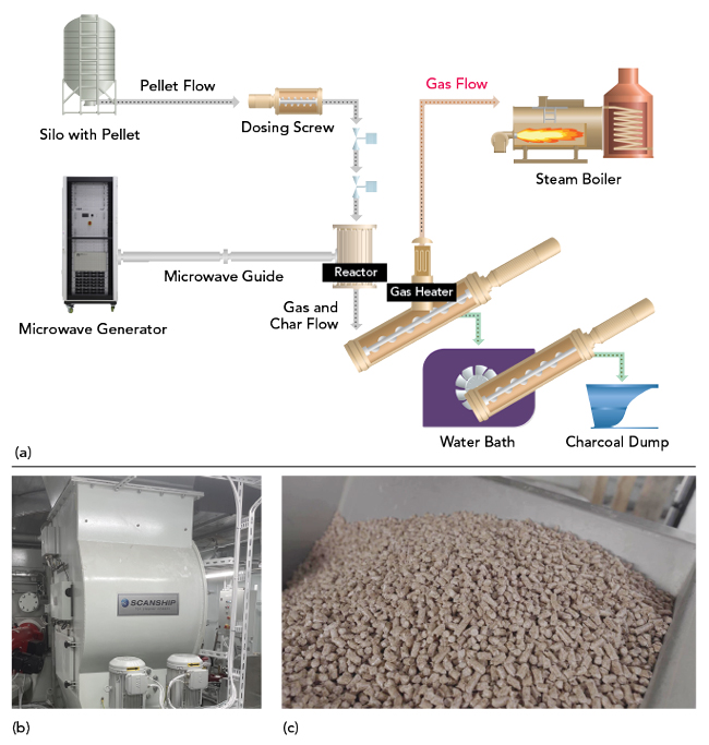
Figure 3 (a) Overview of Scanship’s MAP system. (b) The MAP system chamber. (c) Biochar produced from the MAP system.
MAP System Challenges
In the initial phases of developing their MAP system, Scanship tried using magnetrons as the components for microwave generation. However, they encountered the following challenges:
Inconsistent and non-uniform heating patterns: Magnetrons have inherent issues with providing a stable source of microwave power because of their difficulty in providing a stable frequency signal. Factors such as temperature fluctuations, wear and tear from prolonged use and variations in power supply can cause unexpected shifts in magnetron frequencies. Additionally, due to their fixed resonant structure, magnetrons provide limited control over both frequency and phase.
In the initial versions of Scanship’s MAP system, the magnetrons not only failed to uniformly heat the organic waste, but they also inflicted damage to delicate components caused by the constantly shifting magnetron frequencies. In particular, the spurious harmonics caused electric discharges, which continuously damaged the windows of the pyrolysis chamber. In addition to creating system damage, these discharges adversely affected the quality of the biochar and renewable gas produced.
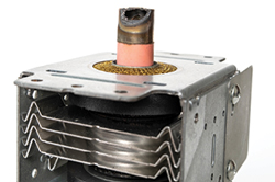
Figure 4 High voltage magnetron failure.
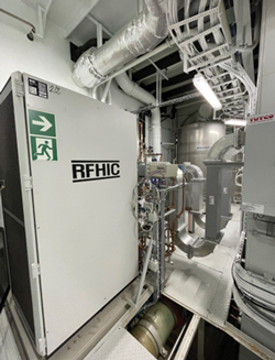
Figure 5 RIK0930K-40TG mounted in the ship.
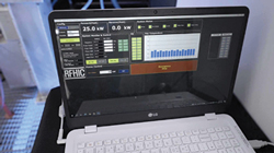
Figure 6 Control software for the microwave generator.
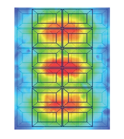
Figure 7 Microwave heat distribution model.
High failure rate over time: Magnetrons typically have short lifespans, lasting from 4000 to 6000 hours of operation. In addition to their limited lifespan, the magnetrons operate at extremely high voltages, often reaching up to 20,000 volts. Because of these factors, users frequently found themselves replacing malfunctioning magnetron units, as well as associated components like circulators, diodes and launchers.
The need for frequent replacements not only escalated operating expenditures, but it also partially offset the magnetron cost savings. In addition, Scanship’s MAP systems are designed to be most useful when the cruise ship is at sea, during a voyage. A failure of magnetron units in the pyrolysis system meant that all operations would come to a halt until the components could be replaced on land. This interruption would result in the ship using backup systems and this reduces efficiency and increases operating costs. An image of a failed magnetron from a MAP system is shown in Figure 4.
THE SOLUTION: REPLACE THE MAGNETRONS
RFHIC was able to solve the issues Scanship was having with the magnetrons by replacing them with the RFHIC RIK0930K-40TG microwave generator that uses GaN-on-SiC solid-state technology for RF power amplification. This system offers 30 kW of output power over the 900 to 930 MHz frequency range. The RF PAs in the RIK0930K-40TG use RFHIC’s internal GaN-on-SiC process. The system comes fully equipped with a three-phase 380 VAC power supply unit, a control module and eight SSPA shelves. Figure 5 shows RFHIC’s microwave generator installed into Scanship’s MAP system.
In addition to the other benefits mentioned, RFHIC’s RIK0930K-40TG provides precise digital control of both frequency and phase. This is a feature that cannot be matched by magnetrons and this allows the Scanship MAP system to adjust the operating environment depending on the composition of the organic waste. The microwave generator also achieved more uniform and consistent heating patterns, allowing the pyrolysis system to process higher volumes of waste in a shorter time. These added features are enabled by RFHIC’s software. Figure 6 shows a representative display of the software used with the microwave generator that is part of Scanship’s MAP system.
The RIK0930K-40TG operates at 50 V, which is much less than the magnetron-based systems that it replaces. It boasts an average lifetime of around 50,000 to 100,000 hours. Each of the eight PA shelves incorporates a redundancy feature to ensure a smooth and gradual decline in performance. In the event of a malfunction occurring in one or two shelves, the microwave generator will continue to function correctly until those shelves can be replaced. The generator is also equipped with hot-swappable power supply units which allows the users to replace any failed packs even while operating.
THE KEY BENEFITS OF RFHIC’S SOLID-STATE GAN TECHNOLOGY
Consistent and Uniform Heating Patterns
RFHIC’s GaN-based solid-state microwave generator produces uniform and consistent heating patterns. This feature is essential to enabling the pyrolysis process and effectively heating the carbon-based waste produced onboard. Figure 7 shows the heat distribution model at 915 MHz and 30 kW of output power.
The GaN-based generator maintains much better frequency stability than the magnetron-based microwave generator. This prevents the unexpected damage to connected components including chamber windows that the magnetrons caused. As a result, these improvements in microwave generation enable higher yields of biochar and renewable gas from the system using GaN PAs. The microwave pyrolysis process described in this article can be used to produce various types of renewable gasses, including hydrogen, syngas and more.
Increased System Lifetimes and Stability
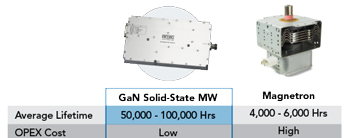
Figure 8 GaN comparison to magnetrons.
As mentioned, solid-state amplifiers have much better lifetimes than tube-based amplifiers. This is certainly the case for RFHIC’s GaN solid-state microwave generator. Figure 8 shows a quantitative comparison of the lifetimes, along with the qualitative comparison of OPEX for the RFHIC solid-state solution versus the magnetron that was previously used in this application.
In addition to the performance and cost advantages, the built-in redundancy feature that the size and weight of the GaN amplifiers allow the microwave generator to continue operating in case one of the PA shelves fails. This adds flexibility in both system design and operation. This feature significantly reduces system malfunctions, which further reduces maintenance and operating costs.
A SUSTAINABLE FUTURE IN MICROWAVE PYROLYSIS
The collaboration between RFHIC and Scanship represents a significant step forward in waste management. With RFHIC’s GaN-on-SiC solid-state microwave technology, Scanship has been able to overcome the limitations of conventional magnetron systems, paving the way for more effective and environmentally friendly waste conversion processes. As the world continues to seek cleaner and more sustainable waste treatment solutions, GaN and solid-state microwave technology serve as a compelling enabler for a greener future.
References
- J. G. Chaffee, U.S. Patent US2147689A, Web: patents.google.com/patent/US2147689.
- J. Koller, U. Baumer, Y. Kaup, M. Schmid and U. Weser, Ulrich, “Analysis of a Pharaonic Embalming Tar,” Nature, October 2003, 425 (6960): 784. doi:10.1038/425784a. ISSN 1476-4687.
- C. Palmer, “Cruise Industry Faces Choppy Seas as It Tries to Clean Up Its Act on Climate,” Reuters, July 2022, Web: reuters.com/business/sustainable-business/cruise-industry-faces-choppy-seas-it-tries-clean-up-its-act-climate-2022-07-27/.