


Figure 8 PSD in dBm/Hz versus frequency (MHz).
Figure 8 graphically shows the mechanism just described. It combines a plot of the power spectral density (PSD) of the 5G NR Band n3 UL, Band n78 UL and the IMD2. We see that overlapping UL signal components in the transceiver create distortion in the DL of Band n3.
Increased Channel Bandwidth RFIC Impairments Causing Desense
Increased 5G NR channel bandwidths in the sub-6 GHz FR1 bands compared to 4G LTE-A create a similar challenge. The channel bandwidth of many of the FDD LTE-A bands being used in 5G NR FR1 has increased without increasing the duplex spacing. This channel bandwidth increase creates additional opportunities for RFIC impairments to impact the transmission output signal quality. If there is coupling between the transmission and receive signal chains, these impairments could impact the receiver sensitivity. Examples of these impairments could be an image signal generated during frequency conversion because of IQ mismatch or LO leakage. The power amplifiers (PAs) in the transmitter could exacerbate the level and bandwidth of these RFIC impairments in the receive band compared to previous 4G LTE-A levels.
As an example, consider 5G NR FR1 Band n28 with an uplink frequency range of 703 to 748 MHz and a downlink frequency range of 758 to 803 MHz. Band n28 is an FDD band with duplex spacing of 55 MHz and 5, 10, 15, 20 or 30 MHz channel bandwidths. An image signal from IQ mismatch or LO leakage may pass through a nonlinear PA resulting in distortion products that overlap the DL receiver frequency range, which leads to desense. Figure 9 shows this path on an RFFE block diagram and Figure 10 shows the third and fifth odd-order IMD products and image power levels, along with the potential desense of the DL receiver in 5G NR FR1 frequency bands.

Figure 9 Band n28 coupling interference from the transmitter UL to the DL receive signal chain.

Figure 10 IMD products and image power levels leading to DL desense.
As described earlier, the desense phenomenon is influenced by channel bandwidth. Figure 11 shows simulated RFIC output, including impairments and non-linearities along with PA transmitter output for a 20 MHz and a 30 MHz channel bandwidth. The red rectangle represents the UL and the blue rectangle represents the DL frequency ranges for 5G NR FR1 Band n28. Figure 11 shows that a 20 MHz channel bandwidth will cause limited DL receiver desense because only a fraction of the final nonlinear products can interfere with the DL frequency range. However, with a 30 MHz channel bandwidth, a larger portion of the fifth-order IMD coming from the RFIC falls in the Band 20 DL. Both the IMD3 and IMD5 products, originating in the RFIC and amplified by the PA, are worse for the increased bandwidth case, which is enabled by 5G NR.

Figure 11 Plots of simulated RFIC and PA transmitter output.
Increased RF Bandwidth and Channel Bandwidth Amplifier Considerations
Besides the potential for self-desense and self-interference, other challenges emerge because of increased RF and channel bandwidths. Selecting appropriate low noise amplifiers (LNAs) for the extremely wide 5G NR FR1 Bands n77 (3300 to 4200 MHz), n78 (3300 to 3800 MHz) and n79 (4400 to 5000 MHz) is a hardware consideration. Each band also supports channel bandwidths as high as 100 MHz per component carrier. There are several options for LNAs in these frequency ranges, each with its advantages and trade-offs. Common source LNAs with inductive degeneration exhibit low noise figures (NFs), but they also have relatively narrow fractional bandwidths. The NFs of common gate LNAs with inductive degeneration are slightly inferior to common source LNAs, but they have wider fractional bandwidths. A programmable LNA is another option, though a designer would need to consider that the tuned performance of these LNAs depends on the carrier frequency. Lastly, a wideband LNA with low NF and high gain may also be suitable, though additional filtering may be necessary. Reasonable wideband gain results from combining multiple LNAs with slightly overlapping bandwidths. This technique is shown in Figure 12.

Figure 12 Overlapping LNA gain and NF to increase bandwidth.

Figure 13 High-level schematic of an ET modulator and PA.
There are other considerations with PAs. High efficiency is desirable and current consumption becomes a significant concern and these challenges become more difficult with wider channel bandwidths. This is especially true for Bands n77, n78 and n79. Envelope tracking (ET) is a common technique to achieve reasonable levels of efficiency. Figure 13 shows a simple ET circuit, but this circuitry and design becomes more complex when channel bandwidths increase beyond 100 MHz. Additionally, it is difficult to avoid asymmetric adjacent channel power leakage ratio issues with many modern PA technologies because of memory effects in the PA.
STEPS TO TACKLE 5G NR RFFE DESIGN CHALLENGES

Figure 14 Example of an RB placement solution for spectrum allocation.
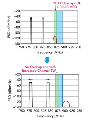
Figure 15 Shifting the UL carrier frequency to minimize self-desense for cell-edge handsets.
Some methods exist to address these RFFE design challenges and some developments are needed. One solution to tackle potential DL desense issues is to use network optimization techniques that involve spectrum allocation with RB placement. This could be part of a larger, intelligent throughput-driven spectrum allocation scheme. Using RB placement for 5G NR FR1 spectrum allocation can result in minimizing UL interactions that could desense DL receivers in the same band or nearby bands. An example of an RB placement solution for spectrum allocation to minimize DL desense occurrences with 5G NR FR1 is shown in Figure 14.
RB placement can be done with relatively simple algorithms and lookup tables. However, cognitive radio techniques have also been proposed to handle real-time spectrum allocation challenges and minimize DL desense more intelligently. Using machine learning/artificial intelligence with cellular resource allocation could enable better spectrum optimization. This might allow planners to consider cellular activity and potential interference from other wireless networking technologies and noise/interference generators. This requires substantial development in cognitive radio technology and protocols for facilitating cognitive networking and cognitive radio interactions.
For specific combinations that may suffer desense or interference from IMD, the UL carrier frequency could be shifted slightly to minimize self-desense for cell-edge handsets. Referencing the example presented in Figure 15 with 5G NR FR1 Band n28, a slight shift of the UL carrier frequency would shift the IMD3 product that would normally overlap with Band n28. This would also allow for increased DL channel bandwidth as shown in Figure 15.
Additional RFFE Technology Developments
To address the changes and growing expectations for 5G NR performance and capability, additional developments are needed in RFFE hardware and systems. To accommodate multi-antenna AAS technology, these developments need to be extremely compact, readily integrated into panelized antenna solutions and more efficient. Wider bandwidth LNAs and PAs are needed to tackle the higher-channel bandwidths possible with FR1 frequency bands. Increased UL power requires high-power tolerance and high efficiency PA designs. More complex 5G NR modulation schemes increase the need for RF block designs with lower error vector magnitudes to ensure that those schemes can be successfully implemented. To reach the speeds and fidelity needed for 5G NR means linearity thresholds must increase for switches, PAs and LNAs to reduce the chance for self-desense. For 5G NR, mitigating self-desense and self-interference solely through RFFE component performance may be impossible. In the long term, the solution may involve adopting intelligent interference mitigation strategies.
CONCLUSION
The 5G NR specifications are consistently pushing the boundaries of wireless networking performance and adopting new features and use cases. These advances, though likely to continue to usher in a new age of connectivity, are also placing new burdens and creating additional challenges that RFFE designers and network optimization engineers must tackle. Ultimately, new strategies and device design/development are needed to address these challenges, but these solutions must also be extremely compact, efficient and cost-effective.
References
- “IMT Vision – Framework and Overall Objectives of the Future Development of IMT for 2020 and Beyond,” International Telecommunication Union, ITU-R Recommendation M.2083-0, Sept. 2015, Web: https://www.itu.int/dms_pubrec/itu-r/rec/m/R-REC-M.2083-0-201509-I!!PDF-E.pdf.
- “NR; User Equipment (UE) Radio Transmission and Reception; Part 2: Range 2 Standalone,” 3GPP, Technical Specification, 38.101-2 V17.7.0.