

Using this technique with a programmable attenuator removes the need to calibrate the signal generator at every power level; the calibrated attenuator will precisely adjust the power level at the output of the calibration plane. This method also reduces the overall uncertainty in the measurement and allows for a calibrated output at extremely low power levels, provided a suitable attenuator with sufficient levels of attenuation is chosen. Any linearity or distortion issues that the signal generator may exhibit at various power levels are mitigated by this technique. This becomes especially important when minimizing the impact of nonlinearities in extremely deep modulation methods used in very high throughput digital data communications.
As mentioned earlier, this approach can reduce the number of calibrations that need to be performed in a specified period. In automated or high volume test environments, this can be extremely advantageous. Additionally, the calibration only needs to be performed at a single power level, rather than the several power level calibrations that would be required without a calibrated programmable attenuator.
Another factor to consider is that the signal generator, test base station or base station emulator will also have a noise floor. This impacts the dynamic range of the test signals. The instrument noise density at low power levels can contain a substantial amount of stimulus energy. Using external attenuators at the output of the signal generator reduces both the noise and signal power and does not introduce any significant added noise. Hence, using an external attenuator at the output of a signal generator can lower the signal level for receiver sensitivity testing, reduce the apparent noise floor of the RF instrument and extend the dynamic range of the test stimulus.
PROGRAMMABLE ATTENUATOR KEY METRICS
Digital programmable attenuators are typically driven by TTL logic signals and exhibit a wide range of attenuation levels with discrete attenuation steps. This type of programmable attenuator generally comes with software tools. These tools may include a complete software suite, application programming interface (API) or some other method of controlling the attenuator. It is important to be able to differentiate between programmable attenuators to select the most appropriate attenuator for a given task. The following is a list of the key metrics of programmable attenuators and brief descriptions of the significance of these metrics or figures of merit.
Key Digital Programmable Attenuator Metrics
- Frequency range (Hz)
- Attenuation range (dB) maximum versus minimum attenuation
- Attenuation accuracy (+/- dB)
- Insertion loss (dB)
- VSWR
- Step size (dB)
- Switching speed (µsec)
- Port impedance (Ohm)
- Interconnect type (coaxial connector style or waveguide)
- RF input power (dB)
- Control method
- DC power supply.
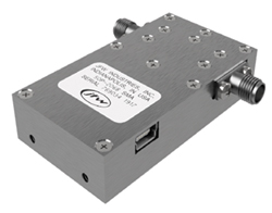
Figure 5 An example of a programmable attenuator with USB control.
Figure 5 shows an example of a JFW Industries programmable attenuator with USB control. A programmable attenuator is generally specified to perform within a given subset of these metrics and form factors over a specified frequency range. The interconnect type and internal architecture of the attenuator are selected to best meet the required performance and mechanical characteristics. For a programmable attenuator, one of the most important characteristics is the maximum and minimum attenuation. Programmable attenuators are generally an arrangement of various switched fixed attenuator sections internal to the module. The attenuation is always referenced to insertion loss. This means that the minimum loss of the attenuator is the lowest attenuation level setting plus the insertion loss of the attenuator. The maximum loss is the sum of all the fixed attenuators within the module and the insertion loss of the attenuator. It is important to note that for most RF devices the insertion loss is a function of frequency and increases at higher frequencies. A programmable attenuator may simply be specified for the “best possible” insertion loss, but a better approach is to specify the insertion loss of an attenuator at various frequency points.
The smallest attenuation step inside the module dictates the least significant bit or the smallest increment in which the attenuation can be adjusted. This is typically either 0.5 or 1 dB for most programmable attenuator models, though some allow much lower resolution steps. The other attenuation states are determined by summing the discrete attenuation steps and the combinations, sequentially, from the smallest to the largest values. For instance, a 63 dB maximum attenuator with a 0.5 dB minimum step size will have attenuation steps of 0.5, 1, 2, 4, 8, 16 and 31.5 dB. This 7-bit attenuator will provide 0.5 dB attenuation increments above insertion loss for all attenuation values between 0.5 dB and 63 dB.
Attenuation accuracy is another critical specification for programmable attenuators used in test environments. The overall attenuation accuracy generally depends on what combination of attenuation steps is used to reach a given attenuation. The higher level attenuation steps are generally less accurate than the lower level attenuation steps, as smaller-value fixed attenuators are generally more accurate than larger-value fixed attenuators.
As the various fixed attenuators within a programmable attenuator are selected using a variety of switches, the speed of these switches dictates how fast an attenuator can shift between attenuation values. With electromechanical relays, this speed may be significantly slower than solid-state switches, which should switch within a matter of microseconds. For high throughput testing applications, such as automated testing of consumer wireless devices, this is a key metric, as it will often contribute significantly to the overall device test time.
The discussion to this point has assumed bidirectional attenuators. In these devices, the RF input power is symmetrical. There are also unidirectional programmable attenuators that are only specified with an RF input power for distinct input ports. When positioned properly, the techniques and characteristics described apply to both types of programmable attenuators.
SELECTING THE RIGHT PROGRAMMABLE ATTENUATOR FOR RECEIVER SENSITIVITY TESTING
The required attenuator performance for a given application depends on the type of receiver that is being tested. This can be very different depending on the receiver type, applicable wireless standards and available test and measurement equipment. For instance, a cellular base station receiver may only need to be tested down to -70 dBm, while a GPS signal may need to be tested down to -140 dBm. These two applications would require very different levels of attenuation depending on the capability of the signal generator/emulator used in the testing.
The noise figure of the receiver and the noise figure of the signal generator also play into the attenuation requirements that may be needed to adjust the apparent noise level of the test stimulus.
There is sometimes a tradeoff in programmable attenuators between attenuation range and attenuation step size. Programmable attenuators with higher attenuation ranges often have larger step sizes. Hence, it may not be advisable to go with the largest attenuation range if high resolution and high accuracy are required. This is not always the case, however, and the lowest step size may vary with the primary application of a given programmable attenuator model.
The frequency range of the programmable attenuator needs to match or exceed that of the receiver under test for receiver sensitivity testing. This is the case unless the receiver is only tested at given frequencies that are well within the receiver frequency range. The absolute attenuation accuracy of a programmable attenuator can generally be offset by calibration. In some rare applications, this absolute attenuation accuracy needs to be as high as possible.
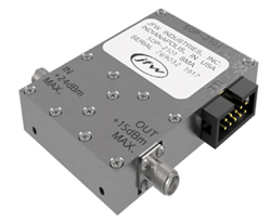
Figure 6 Programmable attenuator with TTL control.
For high throughput automated testing applications or when high-resolution testing of a receiver is needed, fast switching speeds may be desirable. Very fast switching may not be needed for all applications, but having a programmable attenuator that is faster than the requirement enhances the utility of the attenuator for a variety of use cases and test setups. In a laboratory setting with a limited budget, it may be desirable to select programmable attenuators that can serve multiple roles instead of the best fit for a single role.
In some cases, a receiver sensitivity test may be performed in the same or only slightly modified test setup for various other wireless transceiver or system tests. There may be a need for a variable attenuator to accommodate different test techniques. For instance, programmable attenuators are also used in wireless testbeds for throughput testing, handover/fading testing and other test setups for wireless systems, such as multipath testing. A JFW Industries programmable attenuator with TTL control is shown in Figure 6.
CONCLUSION
Digital programmable attenuators are a key element in modern receiver sensitivity testing, as well as a wide range of other test applications. Knowledge of the receiver, RF stimulus and test bed strategy ultimately dictates the required attenuation range and frequency range of a programmable attenuator. Some signal chain analysis and understanding of the wireless standards and specifications is a prerequisite for precisely determining how best to employ a programmable attenuator to solve receiver sensitivity testing challenges.