

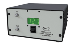
Figure 1 JFW benchtop programmable attenuator assembly with manual and Ethernet/RS-232 control.
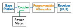
Figure 2 Representative test diagram for receiver sensitivity and dynamic range testing.
With the explosion of connectivity technologies and the thirst for data communicated over wireless channels in virtually every application, from aerospace and defense to consumer handhelds, there is an increased need for testing systems capable of handling the growing numbers of wireless devices being manufactured. To increase the throughput of testing that is both more precise and more repeatable, the reliance on automated testing of RF hardware is greater than ever before. One crucial make-or-break test for many wireless communication and sensing devices is a receiver sensitivity test. This test is especially crucial for critical services such as public safety, fire rescue and military communications, as these services are becoming increasingly reliant on wireless connectivity and are often deployed in some of the harshest environments with the greatest risks.
A key element of modern receiver sensitivity testing is a variable, or programmable attenuator. This article will provide some background on receiver sensitivity testing and programmable attenuators. Additional guidance is also provided in this article to help readers select the most suitable attenuator for receiver sensitivity and related testing. A typical JFW Industries attenuator is shown in Figure 1.
RECEIVER SENSITIVITY TESTING PRIMER
Essentially, the sensitivity of a receiver is the lowest discernable signal a receiver can detect. This results in slightly different definitions for analog/linear receivers and digital receivers. In the case of analog/linear receivers, the signal, noise and distortion divided by the noise and distortion (SINAD) results in a signal level expressed in dB. For digital receivers, the key performance metric is the bit error rate (BER). The BER for a digital receiver is the number of bit errors in the receiver over a unit of time. This performance metric is related to the signal-to-noise (SNR) of the receiver, as well as the quality of the input signal. Typically, digital receiver specifications dictate a certain BER threshold that must not be exceeded for a receiver to be certified or deemed suitable. In some applications, this testing is done to determine the absolute lowest sensitivity of a receiver for operational purposes, as is the case with radar sensitivity being tied to the absolute range of the radar. For packet-based digital communications, the figure of merit is packet error rate instead of BER and is related to the error rate of packets instead of bits.
There are a variety of key receiver sensitivity tests for digital receivers that are a result of the various types of real-world interference. These tests are often baked into wireless standards, including Wi-Fi, Bluetooth, 4G/5G and satellite communications and they will continue to be critical in obtaining certification for wireless receivers. In many cases, the receiver sensitivity is set at a specific level, given a certain SNR, with the sensitivity dependent on the digital modulation type and the code rate. A high level, representative block diagram for receiver sensitivity and dynamic range testing is shown in Figure 2.
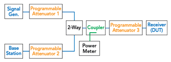
Figure 3 Block diagram for adjacent channel and co-channel interference measurements.
Though related, receiver selectivity requires a slightly different set of tests that are used to measure the receiver performance in the presence of undesired adjacent channel interference and co-channel interference. These tests are also crucial to meet standard specifications and attain certification. They are often lumped into receiver sensitivity testing, as these tests can both be done in similar or even the same test setups. A representative block diagram of the test setup used to measure adjacent channel and co-channel interference is shown in Figure 3.
A challenge with receiver sensitivity testing is that the receiver sensitivity level is necessarily very close to the desired test signal level. To inject interference signals that are precisely controlled, the distortion level needs to be as low as possible. If the distortion of the combination of interfering signals is too high, then nonlinearities in the system may produce spurious signals that are larger than the desired test signal. This could obfuscate the results of a test. This is another area where programmable attenuators are useful in receiver sensitivity testing.
THE ROLE OF PROGRAMMABLE ATTENUATORS IN RECEIVER TESTING
Receiver sensitivity testing requires precise control of RF power levels. This high level of accuracy is a crucial requirement when controlling the stimulus power levels in production tests. These levels must be both precise and repeatable over several testing cycles. External variable/programmable attenuators with precise attenuation values enable input signal control to a device under test (DUT) or system under test (SUT). The ability to precisely control input power levels will reduce the frequency of test equipment calibration and increase the overall accuracy of the tests.
Accurate power measurement during receiver sensitivity testing is also crucial, as even relatively small errors in receiver sensitivity can impact performance in real-world deployments. An example of this requirement is cellular deployments, where the cell coverage is determined by the sensitivity of the base station receiver. This is true for large cellular base station deployments as well as advanced/active antenna system (AAS) base stations. However, in the case of AAS, the receiver sensitivity is also a function of MIMO performance and beamforming performance. With a cellular deployment, the coverage area is determined by the sensitivity of the receiver and any error in this measurement could result in far less actual coverage than was predicted during network deployment.
In addition to creating issues in the field, improper receiver sensitivity testing can create yield, quality and cost issues. In wireless standard compliance testing, an improperly designed and configured receiver sensitivity test may pass underperforming devices or only those with performance well above the specification requirements. Either scenario will directly impact yield and create inefficiencies in the automated testing process that must then be manually corrected at a high cost in terms of time and resources.
A precision programmable attenuator can help address power level inaccuracies during receiver sensitivity testing. Systems like base stations, signal generators and base station emulators tend to be more accurate at higher power output levels and lose some level of accuracy at extremely low power levels. This is problematic for receiver sensitivity testing since the goal is to precisely measure the lowest possible power levels at which the DUT/SUT receiver functions.
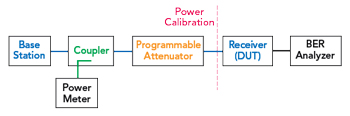
Figure 4 Test setup using external attenuators to enable efficient power calibration.
Figure 4 shows a representative block diagram that addresses this issue. Using a programmable attenuator at the output of the directional coupler, before the DUT/SUT, allows the test setup to have a calibration plane at the output of the programmable attenuator. The purpose of this attenuator is to reduce the signal level from the output of the signal generator to a calibrated low level. In this setup, the coupled output to the power meter can be calibrated for the most accurate range of the signal generator. After calibration, the programmable attenuator can be adjusted for greater levels of attenuation to achieve precise lower power levels.