

ANTENNA RADIATION PATTERN MEASUREMENTS
As can be seen in Figure 2, the vehicle under test is placed on a turntable in front of the reflector. By rotating the turntable, the vehicle will experience an incident wave from different directions, emulating the LOS edge environment. Since the generated field is a plane wave, this results in far-field conditions and far-field parameters such as the antenna gain pattern of a vehicle-mounted antenna can be measured by the test personnel. The gain pattern is measured by connecting one port of a VNA to the antenna on the vehicle and the other port to the RanLOS system to measure the signal transmission. The test setup, with all connections, is shown schematically in Figure 3. To enable rotation, it is preferable that the turntable be equipped with a rotary joint for the RF cable.
The feed array has two ports, one for each polarization. With a 4-port VNA, it is possible to measure both polarizations simultaneously, for up to two vehicle-mounted antennas. If absolute gain values are desired, a calibration must be done first, using a reference antenna with known gain.
As a performance comparison with other measurement methods, Figure 4a shows a Polestar body with a monopole antenna placed on the roof in the RanLOS measurement setup.4 Figure 4b shows the same Polestar body and antenna combination measured in an advanced accredited near-field to far-field (NF-FF) range in Denmark. Finally, Figure 4c shows the gain pattern for the two test setups measured at 2.6 GHz. The agreement between the two test methods is very good. In the NF-FF measurement of Figure 4b, the field is probed in points on a hemisphere around the vehicle and later post-processed to obtain the far-field gain. The time for a measurement using the RanLOS system depends on the instrumentation and the time to rotate the turntable one revolution. The rotation can be done in discrete steps or continuously, in which case, the measurements are taken on the fly. The measurement in the RanLOS chamber in Figure 4a took less than 10 minutes, implying that the RanLOS system can be used as an engineering tool for investigating how the performance is affected by factors such as antenna position, type or manufacturer.
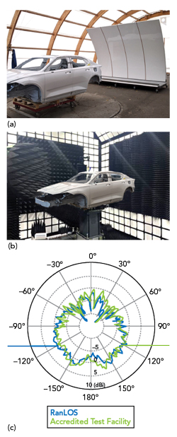
Figure 4 (a) RanLOS system measuring a monopole on the roof of a Polestar body. (b) Monopole on the roof of a Polestar body in an accredited NF-FF antenna test range. (c) Measured antenna gain patterns for the Polestar monopole.
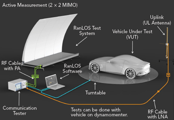
Figure 5 Typical measurement setup when the antenna cannot be accessed.
CONNECTIVITY MEASUREMENTS
In modern vehicles, the antenna is often tightly integrated with the radio module with the consequence that we do not have access to the antenna ports needed for measuring the antenna gain pattern. In such cases, a communication test instrument is connected to the RanLOS system instead of a VNA and OTA measurements of characteristics like the throughput can be performed. A typical measurement setup, in this case for an LTE 2 × 2 MIMO OTA measurement, is shown in Figure 5.
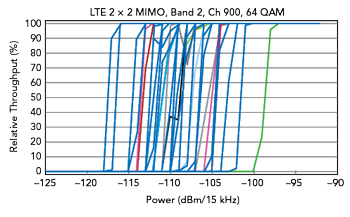
Figure 6 Measured downlink throughput as a function of power and vehicle rotation angle.
In the measurement setup in Figure 5, the communication test instrument, together with the RanLOS system, act as a base station sending a data stream to the antennas and radio modem in the vehicle. This is the downlink. The uplink, which normally is configured to have a lower data speed and modulation scheme, is connected to the instrument via a separate antenna. In Figure 6, several measured downlink throughput curves for the 2 × 2 MIMO LTE system as a function of power for different rotation angles of the vehicle under test are shown.
Each curve corresponds to one angle of rotation of the turntable, representing different incident signal paths as seen by the receiving antennas on the vehicle. As expected, the throughput is at a maximum value for high power levels. When the power is decreased and we approach the sensitivity level of the radio module, the throughput falls to zero very quickly and we lose the connection. From Figure 6, it can also be seen that there is almost a 20 dB difference between the best, leftmost curve and the worst, rightmost curve, cases. In practice, this means that the maximum distance to the base station to maintain connectivity will be different for different orientations of the vehicle to the base station. This delta between best and worst cases translates to a sizable difference in distance. As an example, if the maximum communication distance is 10 km in the best case, it will only be about 1 km in the worst case. This assumes pure LOS communication in free space.
If we have electromagnetic disturbances at the downlink frequency coming from sources in the surroundings or from internal sources in the vehicle, we expect all the curves to be shifted to the right in Figure 6. The consequence of disturbances is that the maximum communication distance will be shorter. The reduction in communication distance will be the same in all directions if the disturbances are coming from the vehicle, but this is not necessarily the case if the disturbances are coming from the surroundings. Due to the large number of electronic control units in modern vehicles, there are many possible sources of disturbances. It is therefore important for vehicle manufacturers to be able to investigate the possible influence of disturbances on the radio communication quality, especially for critical safety systems. Such investigations can be done conveniently in an EMC chamber equipped with a dynamometer so that the vehicle can be run in realistic operation modes. In these cases, the RanLOS test system is a useful tool.
CONCLUSION
RanLOS has developed a unique, patented OTA test system including both hardware and software for measuring antenna performance metrics as well as connectivity quality. The system is mobile, so it can easily be rolled in and out of an existing semi-anechoic chamber, like EMC chambers that many vehicle manufacturers already have. The system should not be seen as a competitor to advanced specially-tailored antenna test ranges, but rather as an engineering tool that can be used regularly to improve antenna performance and connectivity quality, especially for vehicular applications. The system is future-proof in the sense that the frequency range can be extended simply by exchanging the feed array with testing to 3G, 4G or 5G radio requirements determined by auxiliary instruments.
References
- K. Rosengren and P.-S. Kildal, “Theoretical Study of Angular Distribution of Plane Waves in a Small Reverberation Chamber for Simulating Multipath Environment and Testing Mobile Phones,” IEEE Antennas and Propagation Society International Symposium, 2001 Digest, Vol. 3, 2001, pp. 358–361, doi: 10.1109/APS.2001.960107.
- P.-S. Kildal and J. Carlsson, “New Approach to OTA Testing: RIMP and Pure-LOS Reference Environments & a Hypothesis,” Antennas and Propagation (EuCAP), 7th European Conference, 2013, pp. 315–318.
- M. Schilliger Kildal, The Random Line-of-sight Over-the-air Measurement System, Ph.D. Thesis, Chalmers University of Technology, Gothenburg, Sweden, 2020.
- “Simulation and Verification of Wireless Technologies (SIVERT),” Vinnova FFI report 2017–05502, Dec. 2021.