

Vehicles are becoming more dependent on reliable radio communications, whether it be for safety or autonomous driving-related systems or data streaming for software updates or entertainment purposes. The capabilities and performance of these systems and services have become important differentiators in the competition for customers. Even so, only a handful of vehicle manufacturers around the world have invested in test systems to measure antenna performance and connectivity. The main reasons for this are that conventional measuring technologies are complex, often time-consuming to use and require special test facilities, along with large investments. In contrast, the RanLOS test system represents an affordable and easy-to-use alternative solution. The RanLOS system can be used on an ongoing basis during the development process to guarantee reliable and superior performance of the end product. This article explains the ideas and technology behind the RanLOS test system and how it enables vehicle manufacturers to measure both antenna radiation patterns and over-the-air (OTA) data throughput in a cost-efficient way.
BACKGROUND

Figure 1 The RanLOS test system for vehicular applications.
One way to evaluate the performance of a radio communication system is to measure its performance in the actual environment of use. For vehicles, this is normally referred to as a drive test and this simply means that the vehicle is driven around on public roads. This is how many vehicle manufacturers test their systems today. However, this method poses questions; is the environment the same today as it was the last time the measurements were done and are the results comparable? Does the environment represent typical use? Are all the possible cases covered? The answer to all these questions is, strictly speaking, no, bringing into question the value of the tests. Another problem is that a drive test requires a vehicle that is almost finished, which in many cases cannot be driven around in public, at least not during the daytime, due to secrecy. Due to all the practical problems and the limited value of drive tests, other approaches have been proposed. One such approach is to mimic the environment in a laboratory setup. This can be achieved by placing several antennas in a circle, a hemisphere or a similar configuration around the vehicle. These antennas are then fed with suitable signals to mimic a real environment. With such a setup, it is possible to generate waves coming from different directions that simulate reflections, diffraction and scattering from objects in a real environment. The questions then become what environment gets simulated and is this environment the worst case? Another question is how many different types of environments should the test bed emulate to build the confidence level that the test needs have been covered sufficiently.
To begin addressing these questions, the RanLOS founder, Per-Simon Kildal, a professor at Chalmers University of Technology founded Bluetest in 2000. Bluetest made manufacturing reverberation chambers to test mobile devices in rich isotropic multipath (RIMP) environments. The RIMP environment contains many isotropic multipath waves with signals coming from all possible directions, amplitudes, phases and polarizations.1 Professor Kildal began to formulate the idea that to accurately test a communication system, the line-of-sight (LOS) environment must be replicated as well. The LOS environment contains only a single wave incident on the vehicle under test. That environment replicates traditional point-to-point communication links. As he explored these boundary conditions in 2013, Professor Kildal came up with the idea that it would be necessary to test a communication system in both the RIMP and LOS edge environments.2
In 2016, Professor Kildal founded RanLOS to manufacture test systems that accommodated this LOS edge environment. The RIMP environment presents an extreme multipath environment that we rarely see in real life, but which can be emulated in a reverberation chamber. In the LOS edge environment, there is only a single wave incident on the vehicle under test. This is another type of environment that rarely occurs in real life, but Professor Kildal hypothesized that all real environments could be described as something in between these two edge environments. He concluded that if a device is performing well in both edge environments, it will also perform well in a real environment. Also, if a device is not performing well in either of the two edge environments, it will probably not perform well in a real environment, or at least not as well as a device that does better in both edge environments. Since Professor Kildal’s passing in 2016, the theoretical and development work has been carried out by an expert team including his daughter Madeleine.3 Based on these theories, RanLOS has developed OTA measurement systems for vehicular applications as well as for smaller mmWave devices. Figure 1 shows the latest production version of an OTA test system for vehicles.
RANLOS TEST SYSTEM AND APPLICATIONS

Figure 2 The RanLOS test system.
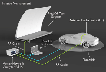
Figure 3 Measurement setup for an antenna radiation pattern measurement.
The RanLOS test system consists of a cylindrical reflector fed by a linear array of dual polarized antennas, along with software for controlling measurement instruments and other peripheral devices. Supported measurement instruments include vector network analyzers (VNAs) and communication test instruments. One example of a peripheral device is a turntable that could also be a 3D positioner. The software controls the measurement steps and collects measured data, as well as performing post-processing and visualizing results in different ways. The feed array is easily exchangeable and it covers an octave bandwidth. To cover the 0.75 to 6 GHz frequency band, the most useful frequencies for vehicular communication systems used today, three feed arrays are needed. RanLOS has developed feed arrays that operate up to 6 GHz. Feed arrays for higher frequencies are on the roadmap, so existing customers can easily upgrade with no need to alter the reflector.
The RanLOS hardware can be viewed as a passive two-port, dual polarized antenna that generates a plane wave at a short distance. In function, it is very similar to the feed horn and spherical reflector used in a traditional compact antenna test range. One advantage of the cylindrically shaped reflector is that it is easier and cheaper to manufacture as compared to a double-curved reflector. It is also scalable in width and can be made in sections.
Figure 2 shows a weather-protected outdoor measurement range with the RanLOS test system in front of a vehicle under test. The vehicle is placed on a turntable so that it can be rotated in front of the reflector. The reflector shown in Figure 2 consists of four identical sections and even though the reflector antenna is physically large, it is equipped with wheels to make handling easier. This makes it possible to conveniently roll the reflector in and out of EMC chambers that many automotive manufacturers already have. The RanLOS setup makes it possible to measure antenna performance and connectivity in an existing chamber.