

A novel hybrid circularly polarized (CP) decoupling method is developed for closely-spaced array applications such as the Beidou Satellite Navigation System array. To realize decoupling between different CP elements, compact coupling lines and novel metamaterial structures are used. By loading with coupling lines, an extra out-of-phase coupled path is introduced and cancelation between the direct and the out-of-phase paths occurs. A miniaturized meta-resonator structure is used as a bandstop choke to cut the direct coupling path, which further improves isolation. A closely-spaced three-element CP array prototype demonstrates a 10 dB impedance band from 1.10 to 1.35 GHz and a 3 dB CP band from 1.25 to 1.31 GHz (covering the Beidou B3 band). Isolation between elements is greater than 23 dB. With a compact size, simple design, high CP isolation and good radiation performance, this hybrid CP decoupling method is suitable for array and MIMO applications.
Array antennas are widely used in radar, satellite systems and wireless communication scenarios due to their high gain and beam-forming characteristics.1 With greater system miniaturization and integration, array element spacing is becoming smaller, leading to stronger coupling between antenna elements.
In the past decade, various decoupling methods have been proposed, mainly divided into the following four categories:
- Defected ground structures.2-5 Half-wavelength resonant slots are etched on the ground to choke the coupling path; however, they usually produce additional backward radiation.
- Neutral lines.6-9 Based on coupling cancelation, a new opposite coupling path is introduced, but its bandwidth is limited.
- Periodic structures.10-13 Surface wave coupling and spatial wave coupling are reduced with periodic structures, such as frequency selective surfaces (FSSs), electronic bandgaps (EBGs) and metasurfaces on the top of the antennas. These, however, are usually large and complex multi-layer structures.
- Decoupling networks.14-16 By implementing a coupling-canceling network between two different antennas, port coupling is well canceled; however, the theoretical design is relatively complex and this technique is limited.
Although much has been accomplished with the above methods, the structures are large and complex. The resulting antenna designs have narrow bandwidths and exhibit poor design flexibility.
Compared with linearly polarized (LP) antennas, CP antennas can improve multi-path distortion and overcome polarization mismatch, making them better suited for satellite navigation and RFID applications.17-19 However, coupling between CP antennas is more serious due to complex coupling paths and radiation limitations. There is limited reported work on mutual coupling reduction in CP arrays.
In this article, a novel hybrid circularly polarized decoupling method is described for the closely-spaced Beidou navigation CP array application. Compact coupling lines are first placed on both sides of the CP elements, which introduces indirect coupling for coupling cancelation. Then, a meta-resonator structure acting as a bandstop choke is located between the elements, so the direct coupling path is well suppressed and isolation is further enhanced.
Using this hybrid decoupling method (cancelation and suppression), a prototype three-element CP array with a center-to-center distance of 0.36 λ0 and an edge-to-edge distance of only 0.11 λ0 is fabricated and tested. The results show that isolation between elements is greater than 23 dB in the Beidou B3 band (1.25 to 1.28 GHz) and good CP radiation performance is obtained as well.
ANTENNA DESIGN
A two-element CP array antenna is first designed to demonstrate the hybrid decoupling method. To obtain high isolation, the two-element CP array is decoupled by using the coupling lines and metamaterials.
Closely-Spaced CP Array Antenna
Figure 1 shows the configuration of the closely-spaced two-element CP array antenna. To lower the profile of the radiator and obtain a stable CP wave, a half-wavelength square patch antenna with a dual-port feed is adopted. The dual-port feed network consists of a two-way Wilkinson power divider and a 1/4 λ delay line (90-degree phase shifter).20 The microstrip patch is printed on a 4.5 mm thick RO4003 substrate with εr = 3.55 and tan δ = 0.0027).
To further reduce the size, the feed network is placed on the back of the patch antenna on a 0.84 mm thick RO4350 substrate with εr = 3.66 and a tan δ = 0.004. The two CP patch antenna elements are placed side by side in the horizontal plane with a center distance of 0.36 λ0 (where λ0 is the free-space wavelength at 1.268 GHz).
To accomplish array decoupling, slender lines with two metallic vias are placed on both sides of the array and a novel meta-resonator structure with multiple shunt inductors and interdigital capacitors is centered between the two elements. The diameter of metallic vias in the coupling lines and meta-resonator is 1.0 mm.
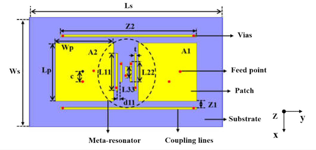
Figure 1 Antenna array with decoupling structure. L11 = 38.5 mm, L22 = 20.9 mm, L33 = 11.4 mm, Z1 = 6.5 mm, Z2 = 140 mm, t = 1.85 mm, d11 = 3.8 mm, Ls = 198 mm, Ws = 113 mm, Lp = 60 mm, Wp = 60 mm, c = 13 mm.
Coupling Lines Decoupling (Cancelation)
The working principle of the coupling lines in Figure 1 is to introduce indirect coupling to cancel out the direct coupling between elements. As shown in Figure 2a, k0 is the direct coupling coefficient from element A1 to A2 before decoupling. When coupling lines are added on both sides of the array, the original coupling is changed with the introduction of additional coupling paths.
In Figure 2b, k1 and k2 represent the new indirect coupling paths, and the original direct coupling path becomes k0'. The total coupling consists of k0', k1 and k2. Due to the structure’s symmetry, the coupling coefficients of two new paths are assumed to be equal, i.e., k1 = k2. If the amplitude in the combined indirect path is equal to the direct coupling path and their phases are opposite, the coupling is canceled.
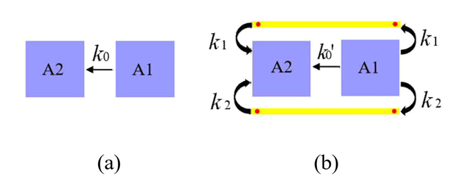
Figure 2 Principle of coupling lines decoupling structure: without coupling lines (a) with coupling lines (b).
Figure 3 shows electric field (E-field) distributions of the proposed two-element array with and without decoupling. Element A1 is excited and A2 is terminated with a 50 Ohm matching load. The E-field distribution on element A2 is weakened after adding the decoupling structure.
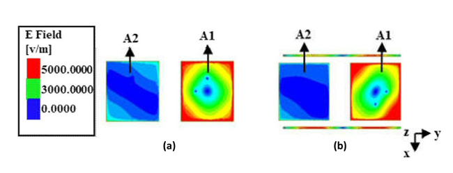
Figure 3 Electric field amplitude before (a) and after (b) decoupling.
Figure 4 shows the results of a parametric analysis of the coupling lines to further illustrate the decoupling principle. As shown in Figure 4a, the smaller the value of Z1 the better the isolation. When Z1 is close to 0.027 λ0 (6.5 mm), the decoupling effect is best. When the length of the coupling lines (Z2) is close to 0.58 λ0 (140 mm), the decoupling effect reaches its peak.
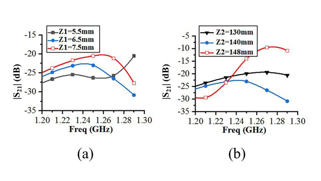
Figure 4 The relationship between Z1 and |S21| (a) and the relationship between Z2 and |S21| (b).
Meta-Resonator Decoupling (Suppression)
To further enhance isolation, a novel coupling suppression method is introduced (see Figure 1). Inspired by the classical split-ring resonator (SRR), a vertical split-ring resonator structure is implemented between different array elements.21-23 When the meta-resonator is in a resonant state, it can be seen as a bandstop choke and the direct coupling path between adjacent elements is cut.