

Figure 1 AIP system construction. Source: pSemi
A phased array antenna aggregates many antenna elements to form a large array that uses beamforming to increase the directional gain, with the effective isotropic radiated power (EIRP) characterizing the power and reach of the phased array. The directional gain compensates for signal fading, enabling applications to benefit from mmWave’s high bandwidth and low latency. As such, phased arrays have been widely adopted for 5G and satcom applications, with MIMO, multi-user MIMO (MU-MIMO) and massive MIMO (mMIMO) architectures enabled by beamforming and beam steering technologies to increase network capacity and improve the user’s experience.
To minimize size and achieve the best performance, many systems adopt the compact antenna-in-package (AiP) architecture, where the phased array antenna and components such as beamformers, power amplifiers and up- and down-converters are all integrated (see Figure 1). The only way to test a mmWave AiP system is OTA, since the AiP system is a single, compact package with many RF channels and no RF connectors at the antenna elements. Beam steering is a key factor for successful performance. To guarantee beam steering performance, OTA testing must evaluate the AiP’s characteristics, such as radiation pattern and the relative gain and phase of the elements.
TRADITIONAL OTA TESTING

Figure 2 Direct far-field test setup.
With the adoption of 5G and satcom, more systems and devices are moving to mmWave frequencies. Depending on the system architecture and antenna design, devices for these applications have varying sizes and shapes; OTA measurement of the antenna system requires an anechoic test chamber, where the size of the chamber depends on the size of the device. For 5G systems, several measurement options are defined by 3GPP:
Far-Field Measurement Options
The 3GPP TR 38.810 specification defines the direct far-field (DFF) technique, which requires a minimum measurement distance (see Figure 2), where the spherical wave from the source is transformed into a plane wave for radiation pattern measurements. The DFF method generally requires larger test chambers based on the diameter and operating wavelength of the AiP module. For example, a 28 GHz device with an antenna dimension of 15 cm requires a 4.2 m chamber to achieve far-field measurements. The larger the chamber, the higher the cost, the greater the space and added test time due to the mechanical operation of the chamber.
A compact antenna test range (CATR) uses the indirect far-field (IFF) method to reduce the size of the test chamber (see Figure 3). The CATR system uses a parabolic reflector to parallelize the wave from the feed horn to create a far-field test environment. Although the distance between the device under test (DUT) and the feed antenna is essentially halved, the entire CATR system still requires a chamber box of significant dimensions. In addition to chamber size, the CATR setup slows measurement time, typically taking 10 to 20 minutes.
To measure a 3D sphere radiation pattern, the testing methods for traditional DFF chambers and IFF CATR include rotating the DUT in azimuth and elevation to obtain full pattern measurements. This requires the DUT to be mounted on a rotating table stepped by electric motors, often taking hours to generate a complete 3D antenna pattern—with the potential for interference or other limitations caused by the motors.
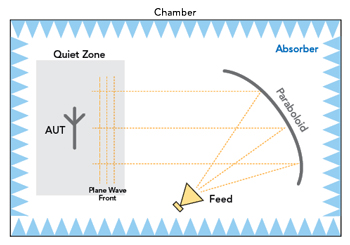
Figure 3 Indirect far-field test setup using a CATR.

Figure 4 OTA testing using a horn antenna.
Horn Antenna Measurements
AiP testing using a horn antenna is faster and more cost-effective for mass production testing (see Figure 4). However, it only measures the total radiation peak power at a fixed angle. Even with three horn systems, each horn in a different position, the testing angles and dimensions are limited. Since the AiP is a phased array with many antenna elements, each with configurable gain and phase, only measuring the gain in a few directions yields uncertainty in assessing the antenna pattern and guaranteeing the performance of an AiP system.
OTA testing requires a stable and well-calibrated testing environment. As noted, available chamber-based test solutions provide comprehensive measurements, but the chamber is bulky and costly, and the tests are time consuming. The rotation of the turntable is slow, susceptible to interference and may be limited. This doesn’t make sense for production lines. While the horn test approach is widely adopted in production, assessing the spatial coverage of the AiP is a significant gap.