
To ascertain the correct physical thickness of the dielectric, the electrical length is assumed to equal the refraction index multiplied by the physical thickness; and as loss tangents for radome materials are low, this can be further simplified to equal physical thickness multiplied by the square root for the dielectric constant. Resolving the accumulated phase of the second reflected wave against the required phase change for cancellation equals the following:
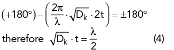
where λ is the free space wavelength, Dk represents the dielectric constant of radome and t is the physical thickness.
When done correctly, and at a normal angle of incidence, this solution can provide extremely low losses with the required structural support for environmental protection. However, this construction type greatly suffers when either high angles of incidence are expected or wide bandwidth systems require multiple frequencies to pass through unimpeded.
A sandwich laminate operates in much the same way but with additional boundary interfaces. Griffiths1 and others have cited that the ideal construction for cancellation is a core thickness of a quarter wavelength; however, this rule of thumb is only an approximation, and the interaction is more accurately described by Mazlumi.2 With the approximation of an air core, the following condition emerges for maximum transmission (eq. 23 Mazlumi, 2018):
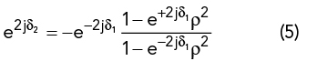
where j=√(-1), δ1 (resp. δ2) the one-way phase accumulation 2Π∨λ·t·√Dk through the skin (resp. the core) and ρ is the transverse reflection coefficient at the air-skin interface.
If the skin is electrically negligible (e±2jδ1 = 1), the electrical thickness of the core has to be a quarter wavelength for maximum transmission. However, if the skin is not absolutely electrically thin or the core has a refractive index ncore≠1, the condition is no longer met and a numerical optimization of the thicknesses has to be used to get the best transmission.
FABRICS IN HIGH FREQUENCY RADOMES

Figure 3 The reflected vs. transmitted wave relationship of an electrically thin radome.
Fabrics have been traditionally used in much larger air-inflated radomes that use positive pressure to retain structural integrity. For high frequency systems, they have been redesigned to optimize for the new application. The fabric composite is constructed from high strength aramid fibers (Kevlar®) with a blended fluoropolymer matrix. The aramid fibers are oriented in a flat, plain weave for enhanced flexural characteristics and high tear strength specifically for use in radome applications. The blended fluoropolymer matrix uses polytetrafluoroethylene (PTFE) and fluorinated ethylene-propylene (FEP) to provide optimum hydrophobicity preventing water accumulation and actively encouraging rain to slide off the exterior surface.
Much like other radome constructions, their behavior with an incident signal is governed by the same physical principles demonstrated with monolithic plastics in Figure 2; with the key difference being their extremely reduced thickness. A radome can be defined as being electrically thin if the thickness of the dielectric material is less than approximately one tenth the signal’s wavelength in free space (t < 0.1λ). Under these conditions, the radome works to achieve the required 180-degree phase difference by minimizing the distance traveled by the second reflected wave so that the subsequent accumulated phase shift is negligible. This is illustrated in Figure 3.
The structural fabrics used in radome applications have a total nominal thickness of 0.008” [0.20 mm] compared to approximately 0.200” [5 mm] in monolithic plastics, where the additional thickness is necessary to provide the required structural performance. The importance of this thickness difference is correlated closely to the wavelength of the signal passing through and illustrates why high frequency applications require new radome solutions.
At 1 GHz (the approximate frequency of 4G telecommunications), the signal passing through the radome has a wavelength of 300 mm. This long wavelength makes both plastic- and fabric-based systems qualify as electrically thin (tplastic = 0.0167λ and tfabric = 0.0007λ) and so the degree of phase change through either system is negligible. However, at 40 GHz (the high end of current 5G mmWave applications), the signal’s wavelength is now only 7.5 mm and so only fabric-based systems continue to behave as an electrically thin dielectric (tplastic = 0.67λ and tfabric = 0.03λ). The importance of this difference is seen when analyzing the total transmission loss of each radome type at a specific frequency. Figure 4 shows an optimized design of each style of radome tuned to the bottom of n260 band within 5G mmWave frequencies.

Figure 4 Three radome constructions tuned for optimum performance at 37 GHz frequency at 0° angle of incidence.
The impact of thickness can be seen where the monolithic plastic (blue) has a designed electrical thickness equal to half wavelength to tune to the desired 37 GHz frequency versus the tensioned fabric (green) for which the loss remains low as maximum reflections occur at much higher frequencies. This fundamental difference of behaving like an electrically thin dielectric even at high frequencies allows fluoropolymer fabrics to be band agnostic and provide low loss across a wide frequency range. The sandwich composite (orange) plot shows how adding additional skins on either side of an electronically invisible core can provide additional wide bandwidth benefits at 0-degree angles of incidence.
Up until now, every electrical situation has analyzed the impact of a radome at normal incidence angles, but this is rarely true in real world applications. The angle of the incident signal can create additional transmission losses if deviating too far from normal. Although the proximity to the emitting signal adds complexity in understanding the impact of these angles, its effect can be simplified by equating it to the changing geometry the transmitting wave experiences.
For tuned radome systems, such as the existing sandwich and monolithic technologies, this change in geometry increases the amount of material the wave must travel through and so increases the accumulative phase of the second reflection. If this incidence angle is significant, it will cause the second reflected wave to no longer cancel the amplitude of the first wave and create significant signal attenuation. The effect a 60-degree incidence angle has on each technology is shown in Figure 5.
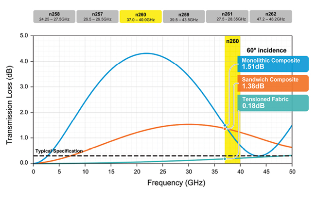
Figure 5 Three radome constructions tuned for optimum performance at 37 GHz frequency at 60° angle of incidence.
The final electrical parameter important to radome performance is its ability to minimize water accumulation on the surface in the form of rain, snow or ice. This is arguably the most critical function of a high performing radome as water has such high attenuation properties compared to typical radome materials, that even a small amount can create tremendous signal degradation. The high dielectric constant (approximately 25× higher than typical radome materials) will create additional reflective losses; while the increased loss tangent (approximately 30×) will create absorption losses typically made negligible using low loss materials. At frequencies in the mmWave band, these losses can easily exceed 1 dB rendering even a well-designed radome unusable.
Fluoropolymer fabrics are inherently hydrophobic and are specifically designed to prevent water accumulation by maximizing the mobility of water on their surfaces. Hydrophobicity is typically defined as a surface that creates a > 90-degree static contact angle with a polar molecule, with any angle < 90-degrees defined as hydrophilic. While this definition has served many industries well in the past, the static contact angles of hydrophobic materials do not always correlate well with signal attenuation in wet conditions because those measurements fail to account for the impacts of surface texture and micro features on water droplet mobility. The fabrics presented here combine a uniquely effective blend of fluoropolymer compounds, woven fabrics and engineered surfaces to provide not only conventionally defined hydrophobic surfaces, but surfaces that have been proven to increase the likelihood of water runoff.
Drop mobility can be quantified by choosing a fixed surface angle and assessing the mobility of water droplets of different volumes to determine which stay pinned and which are mobile. Figure 6 compares ABS (a typical monolithic plastic radome material) to a fluoropolymer fabric in the case of a completely vertical (90-degree incline) surface. In this study, it was seen that water droplets up to 26 μL in volume stay pinned to an ABS surface, while any water droplet > 8 μL is mobile on a fluoropolymer fabric surface. This increased drop mobility promotes enhanced water shedding and minimizes subsequent signal degradation.

Figure 6 Water mobility as a function of droplet volume on an ABS surface and on a fluoropolymer fabric surface.
SECONDARY BENEFITS OF FABRIC RADOMES
Fluoropolymer fabrics have two additional benefits over the incumbent technology that do not relate to their electrical performance. First, they are naturally UV stable compounds to offer enhanced performance over a given lifespan and second, they are less thermally conductive than their incumbent counterparts and so dissipate heat at a faster rate.
Fluoropolymer fabrics, in some capacity, have been used in radome applications for decades as a naturally inert PTFE compound that can resist environmental weathering without the need for repair or replacement. For high frequency fabric radomes, this technology has been compounded with highly effective UV blockers that enable the strong aramid weave to remain fully protected, ensuring lasting structural integrity while retaining its hydrophobic properties for the full life of the radome.
Their thermal advantage is a function of a greater stiffness combined with lower thermal conductivity. Fluoropolymer fabrics subjected to ASTM D5470 testing yield a thermal conductivity of 0.18 W/mK, which combined with a nominal thickness of 0.20 mm gives an R-value of 0.011 m2K/W. For a well-designed monolithic plastic or sandwich composite radome, the comparative R-values will be approximately 3× and 6× higher, respectively, than any fabric solution. By dissipating heat at a faster rate, fluoropolymer fabrics can minimize the need for complex cooling systems, extend the life span of underlying electronic equipment by reducing the ambient operating temperature and help melt snow and ice from the surface during inclement weather.
References
1.L. Griffiths, “A Fundamental and Technical Review of Radomes,” MP Digest, 2008.
2.F. Mazlumi, “Analysis and Design of Flat Asymmetrical A-Sandwich Radomes,” Journal of Telecommunication, Electronic and Computer Engineering, Vol. 10, July 2018, pp. 9-13.