
The best radome is no radome. But when one is needed, it is required to protect the underlying electronic equipment from the outdoor environment while creating as little attenuation as possible to the transmitting signal. Radomes have historically been used in one of three applications: 1) aerospace, 2) large ground installations operating at high frequency and 3) simple shrouding used for low frequency telecommunications. With the onset of 5G mmWave applications, many IoT use cases, LEO Internet and increased backhaul applications, numerous communication technologies are poised to take over this market, all of which are operating at higher frequencies than their incumbent technologies.
Higher operating frequencies have several advantages over low frequency systems; but at the core of why they are synonymous with new use cases is that they allow the system to carry more data, at faster speeds, for a greater capacity of users. These benefits are critical to the viability of almost all use cases, but they do cause significant challenges that the new infrastructure must overcome.
RADOME OPTIONS
Historically, there have been two main construction options for telecommunication radomes: 1) single layer monolithic materials, such as glass reinforced thermosets or thermoplastics and 2) multilayer sandwich composites, which use structural skins on either side of an electrically invisible core to limit the amount of signal blocking material. These solutions are well suited to current low frequency technology; however, they experience significant electrical and thermal limitations at higher frequencies. Therefore, a third construction type has been developed and is introduced here: 3) structural fabrics tensioned by a supporting frame. All three options for high frequency radomes are shown in Figure 1.

Figure 1 Radome construction options for use in high frequency applications.
The primary function of a radome is to protect the underlying electronics while not impeding the transmitted signal; and the effectiveness of any radome is largely governed by understanding their impact on the transmitted and reflected waves. All radomes are comprised of dielectric materials that are defined predominantly by their dielectric constant (Dk), dissipation factor (Df) and their associated thicknesses. For a signal passing from air through an isotropic, homogenous dielectric with negligible magnetic field properties, the impedance of free space and of the dielectric is defined as follows:
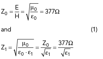
where Z0 is the impedance of free space, Z1 is the impedance of dielectric, E is the electric field strength, H is the magnetic field strength, μ0 is the magnetic constant (permeability of free space) and ε0 is the electric constant (permittivity of free space).
As an incident signal is transmitted through a monolithic dielectric, it experiences two changes in medium: the first at the free space/dielectric boundary as the wave enters the radome, the second at the dielectric/free space boundary as the wave exits the radome. Both interfaces create a reflected and transmitted wave; and both create loss through a combination of reflection and absorption. The ratio of losses created is governed by the reflection and transmission coefficients that are defined as follows:
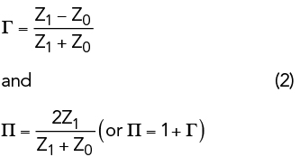
where Γ is the reflection coefficient and Π is the transmission coefficient.
As radomes intentionally use low loss materials, it is the reflective loss rather than absorption that governs the overall performance; therefore, the purpose of a radome can be simplified to a device that uses its construction to cancel out the complex amplitude of the reflected waves so that virtually no energy is sent back to the transmitter. There are an infinite number of reflected and transmitted waves inside the dielectric, but if a first order approximation is assumed, this cancellation is achieved by matching the thickness to half the signal’s free space wavelength, or a multiple thereof, as designated below:

where φ1 is the accumulated phase of first reflection, φ2 is the accumulated phase of second reflection and Δφ is the desired phase difference.

Figure 2 The reflected vs. transmitted wave relationship of an electrically thick radome.
In calculating the accumulated phase shift of the first reflected wave, it is important to note that a reflected wave naturally experiences a +180-degree phase shift when crossing from a medium of a lower refraction index to one with a higher refraction index, i.e.: when trying to enter the radome. By designing the electrical thickness of the radome to exactly 0.5λ, the second reflected wave has naturally undergone +360 degrees of phase change via the two-legged journey through the radome and achieves the +180-degree difference required for cancellation. This behavior is graphically illustrated in Figure 2.