
Noise sources are some of the most versatile devices used to measure and monitor the performance of microwave and mmWave components and systems. As external signal sources, they are commonly used with spectrum analyzers and other test equipment to determine the noise temperature, noise figure or frequency response of individual components and integrated receivers. Also, they are frequently teamed with built-in test equipment in radar, telemetry and communication systems where automatic calibration and system monitoring are required. In most applications, noise sources work best when they have flat and stable spectral characteristics. When they are integrated into mmWave subassemblies, small size is a major consideration.
Eravant’s STZ noise sources cover wide portions of the microwave and mmWave spectrum, operating from 500 MHz to 170 GHz and with excess noise ratios (ENR) from 12 to 20 dB. The latest additions to this product family include the -02 and -0T2 series compact noise sources shown in Table 1. They provide flat ENR over wide bandwidths and are housed in small packages that facilitate their inclusion with portable test equipment or in compact hardware. With nominal ENRs of 15 to 18 dB, these noise sources provide calibrated noise power from 0.5 to 67 GHz. Typical ENR flatness is ±2 dB over the operating bandwidth and nominal output return loss is 15 dB for most models. For broadband system testing, ENR flatness is important because correcting or compensating for variations in the noise spectrum can be extremely challenging. Each noise source includes an integrated attenuator that controls its output impedance and reduces measurement uncertainty from impedance mismatch. The attenuator eliminates the need for a costly external isolator. Each noise source is enclosed in a slim package that measures 4.0 × 1.2 × 0.8 in. and weighs 9.2 oz.
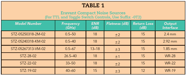
The models with coaxial output connectors cover extremely wide bandwidths: continuous frequency coverage from 0.5 to 40 GHz with a K connector (see Figure 1), 0.5 to 50 GHz with a 2.4 mm connector and 0.5 to 67 GHz with a 1.85 mm connector. Current waveguide output options comprise WR28 (26.5 to 40 GHz), WR22 (33 to 50 GHz) and WR19 (40 to 60 GHz). The WR22 and WR19 versions have anti-cocking waveguide flanges (see Figure 2).

Figure 1 Noise source STZ-05267313-VM-0T2 operates from 0.5 to 67 GHz and has a high speed TTL trigger input for automated test applications.
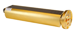
Figure 2 Noise source STZ-05267313-VM-02 operates from 40 to 60 GHz and has a UG-383/U-M anti-cocking flange.
The noise sources are biased with a supply voltage of +28 V and can be modulated by switching the DC power on and off, up to 1 kHz. Models with the -0T2 option have a high speed TTL control input and a toggle switch to support automated test setups, laboratory applications and equipment where the noise source is built in.
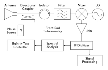
Figure 3 Using a noise source for built-in test can calibrate a receiver’s response and monitor the health of individual components.
Their compact size makes the -02 and -0T2 series noise sources well-suited for the built-in test equipment used in radar, telemetry, radiometry and communication receivers. By including a noise source and a directional coupler in a receiver’s front-end signal path, the receiver can perform self-calibration and monitor the health of various system components (see Figure 3). The frequency responses of filters and gain blocks can be verified by injecting wideband noise into the receiver while performing a spectral analysis of the down-converted IF signal. Detected noise levels can also be used to reveal elevated local oscillator (LO) noise sidebands, spurious outputs in the LO signal or problems caused by a mixer’s limited image or sideband signal suppression.
Noise sources have many other uses. They are frequently employed to measure the bit error rate of digital communication links. By independently varying the power levels of both the signal and noise, the effects of mixer saturation and amplifier compression can be quantified to establish a receiver’s dynamic range or estimate its vulnerability to interference under various operating conditions. For measurements that do not require high dynamic range, an amplified noise source can be used with a spectrum analyzer to characterize the frequency response of amplifiers, attenuators, isolators and devices where low insertion loss and relatively flat frequency responses are common characteristics. Such a test system can be used with a pair of transmit and receive antennas to measure the reflectivity of surfaces or the attenuation of signals through materials without requiring a costly tracking signal generator or low loss mmWave transmission lines.
mmWave noise sources have many potential uses in systems, ranging from built-in test equipment in radar and communication receivers to laboratory instrumentation. By combining excellent ENR flatness with compact, flexible and cost-effective packaging, Eravant’s -02 and -0T2 series of noise sources help mmWave system developers cover more spectrum using less equipment. Standard coaxial connectors and Uni-GuideTM waveguide connectors made the compact noise sources more cost-effective by sharing the same package designs to support component and system testing from 0.5 to 67 GHz.
Eravant
Torrance, Calif.
www.eravant.com