αn = 180 degrees represents the point of resonance, and its slope gives the FBW. Thus, EV, MS and CA are the essential characteristic parameters that determine the radiation characteristics of the structure and the CMs contributing to radiation. The Eigen currents and the fields are orthogonal; hence, CMs radiate independently of each other and can be used as basic functions to expand the total current (J):

In Equation 11, Vin is the MEC, which assesses the effect of the applied excitations’ position, phase and magnitude on a particular CM’s contribution to the net radiation.
MSA Design
An MSA is modeled (see Figure 2) using simple closed-form expressions16 and analyzed using TCM. All possible mode excitations are determined over the range from 2.5 to 4.5 GHz. Figures 2a and b plot the EV and MS versus frequency. Five numbers of CMs are considered, J1 to J5 (mode indices from 1 to 5), chosen per the criterion in Equation 12:

In Equation 12, NM is the total number of stable CMs, No is the number of CMs achieving, MS ≥ 0.707 and po is the accuracy factor.
Figure 2 shows that two modes, J3 and J4, contribute over the complete band with resonances near 3.3 GHz (MS ∼1). Figure 2b shows that J3 covers 2.6 to 4.5 GHz (FBW = 53 percent) and J4 covers 2.8 to 4.2 GHz (FBW = 40 percent). Figure 2c plots the respective 3D radiation pattern and surface current distributions. J3 is the dominant mode giving the desired radiation pattern and J4 is a higher-order mode.
U-Slot Design
A U-slot is modeled (see Figure 3) using Babinet’s principle of duality,39 considering it as a metallic U-strip on a dielectric substrate. Figures 3a and b plot EV and MS versus frequency. Six modes are considered, i.e., J1 to J6 (mode indices from 1 to 6). Figure 3 shows that mode J2 contributes from 2 to 4 GHz (FBW = 75 percent) and the other modes, except J3, show capacitive behavior. Figure 3c shows the 3D radiation pattern and surface current distribution plots for J2. The mode J2 is dominant and gives a desirable radiation pattern.

Figure 3 Slot antenna EV (a) and MS (b) vs. frequency; radiation pattern and surface current distribution (c).

Figure 4 UMSA EV (a) and MS (b) vs. frequency; radiation patterns and surface current distributions (c).
U-Slot MSA (UMSA) Design
The UMSA is designed, combining MSA and U-slot designs, and the overall structure is shown in Figure 4. Figures 4a and b plot EV and MS versus frequency. Five modes are considered, i.e., J1 to J5 (mode indices varying from 1 to 5), and the figure shows that modes J3 and J5 contribute to the band of interest. Figure 4c plots the respective 3D radiation pattern and surface current distributions for modes J3 and J5 showing J5 provides the desired current distribution.
A probe excitation with a diameter of 1.35 mm is modeled to see its effect on CM propagation. Figure 5 plots the MECs versus frequency, confirming J5 as the desired radiation mode with a higher value of MEC near the resonant frequency. The inset in Figure 5 shows the surface current distribution, illustrating the in-phase coupling between the U-slot and the dominant TM10 mode of the MSA.14 The current distribution is maximum around the slot near the edges of the MSA.

Figure 5 UMSA MEC vs. frequency.

Figure 6 UMSA reflection coefficient magnitude vs. frequency.
Figure 6 plots the magnitude of the reflection coefficient, |Γ|, versus frequency using the standard Method of Moments (MoM) simulation. It shows that the desired bandwidth is achieved with resonance at 3.3 GHz. Note that the resonance point differs slightly from that determined with TCM.
The next section validates the design with two of the most promising and proven techniques available in prior literature40,41 to show TCM’s accuracy and effectiveness.
UMSA Design Validation
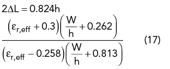
The initial UMSA design is obtained from closed-form empirical expressions using the dimensional invariance (DI)41 and three resonant frequency (TRF)40 techniques. TRF defines the criterion of choosing εr and h depending upon the desired FBW = 100 (fres2-fres4)/ fres3, where fres2 and fres4 are the lower and upper bounds of the VSWR bandwidth (2:1) and fres3 is the center frequency. The substrate thickness, h, must satisfy the criterion in Equation 13. Initial design parameters of the UMSA are chosen using Equation 13 to Equation 20 depending upon desired VSWR bandwidth40 (see Figure 1).


Ls is selected such that


The DI method41 predicts that the only parameter dependent on substrate choice is W/h, and all other-dimensional parameters (see Figure 1) follow a constant ratio, as given in Table 1. A variation of W/h with frequency is studied and its empirical relationship is derived for the chosen substrate as

