
Figure 4 illustrates the measured arrival times of peaks of the channel impulse response for SSB-indices 0 and 2 of two cells (PCI 75 and PCI 362) at SSRef 3,574.56 MHz (Case C). The measurement is primarily interested in the arrival time difference to the first measured peak to measure the delay spread. The measurement confirms the expectation11 that the SSB with index 2 is transmitted 500 µs later than SSB with index 0. From Figure 4, the distribution of the peaks indicates how much reflection and scattering occurred with higher delay spread for index 0. The signal of the cell with PCI 362 arrives approximately 2 µs later than the one from the other cell with PCI 75, which is mainly caused by the larger cell-to-receiver-distance for PCI 362.
CHALLENGE 2: NETWORK SYNCHRONIZATION MEASUREMENTS
Ensuring base station synchronization is a critical component for successful network deployment. If a base station is out of sync, the handover of active connections will fail, leading to dropped calls for the user and a poor user experience. For TDD, the synchronization requirement is particularly crucial, as a time offset can lead to an overlap of uplink and downlink time slots, impacting base station performance and interfering with correctly synchronized neighboring base stations (see Figure 5).
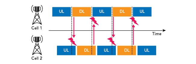
Figure 5 Interference between two cells.
The allowed time alignment error is specified by the 3GPP (Release 15, Section 6.5.3). To ensure proper synchronization, the cells receive their reference time from the network or via a connected GNSS receiver.8 Networks of different operators must be synchronized to avoid interference due to intermodulation products between networks on neighboring frequencies. This enables all operators to minimize interference.
Previously, these timing measurements were performed with a spectrum analyzer and special test ports on the base station, requiring cabled measurements. In 5G NR, the common deployment of remote radio heads and active antenna systems without special test ports makes conventional timing measurements difficult and requires over-the-air timing measurements.
To verify the time synchronization of a network, the proposed scanner uses two possible measurements of varying precision: 1) a time of arrival (ToA) measurement of the received SSBs and 2) a time alignment error (TAE) measurement of the received SSBs. The ToA measurement provides a time stamp for the received SSB. This provides a good indication whether a certain base station cell is out of sync compared to other base stations received. The ToA measurement provides a precision of about 400 ns. To achieve higher precision and fulfill the coordinated universal time (UTC) second synchronicity requirement, a TAE measurement is used.
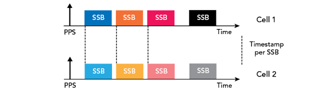
Figure 6 UTC synchronized base stations.
For the TAE measurement, line-of-sight (LoS) to the cell is required where the distance between measurement antenna and cell antenna is known—which can be measured with a laser range finder—together with good GPS reception or an external time base as the time reference. The receiver/scanner can calculate the UTC transmission time of every received SSB as well as the frequency error of the cell (see Figure 6). Measurement precision is then dependent on the provided reference of the integrated GNSS receiver. Good GPS reception yields a time accuracy below 30 ns. From the known distance between measurement position and base station, the transmit time can be calculated, identifying timing issues rooted in the setup of the base station. Experimentally, it has been verified that the following conditions need to be fulfilled to enable such a precise measurement:
- The signal from the measured base station must have a SINR above 15 dB
- The delay spread needs to be below 17 ns, which is used as indicator for LoS
- To obtain best performance with a GNSS receiver, movement faster than 30 kmph is recommended to remove reflections from the received signals.
- A high accuracy pulse per second (PPS) signal must be available, either from the GNSS receiver or an external connection
- The PPS signal needs to provide higher accuracy than the internal time base
- The GNSS receiver must report a valid UTC time synchronization.
CONCLUSION
This article demonstrated how to use a passive scanner for measurements in 5G NR networks, with special attention to network synchronization in both the FR1 and FR2 bands. Methods for the measurement of network coverage, network synchronization and channel impulse response were proposed and are straightforward to implement. An approach for ACD to find the relevant carrier frequencies for 5G MNT in networks with an unknown configuration was presented. Finally, the proposed methods were applied for deployed 5G networks to demonstrate effectiveness.
References
- X. Lin, J. Li, R. Baldemair, T. Cheng, S. Parkvall, D. Larsson, H. Koorapaty, M. Frenne, S. Falahati, A. Grövlen and K. Werner, “5G New Radio: Unveiling the Essentials of the Next Generation Wireless Access Technology,” IEEE Communications Standards Magazine, Vol. 3, No. 3, September 2019, pp. 30-37.
- S. Ahmadi, “5G NR: Architecture, Technology, Implementation, and Operation of 3GPP New Radio Standards,” Academic Press, 2019.
- M. Kottkamp, A. Pandey, D. Raddino, A. Roessler and R. Stuhlfauth, “5G New Radio: Fundamentals, Procedures, Testing Aspects,” Rohde & Schwarz, 2019.
- “3GPP Technical Specification TS 38.101-1, NR; User Equipment (UE) Radio Transmission and Reception; Part 1: Range 1 Standalone,” 3GPP, V16.8.0, June 2021.
- “3GPP technical specification TS 38.101-2, NR; User Equipment (UE) Radio Transmission and Reception; Part 2: Range 2 Standalone,” 3GPP, V16.8.0, June 2021.
- A. Sibila, “5G NR Network Rollout is Now – Let’s Test!” Microwave Engineering Europe, July 2019.
- M. Mielke and M. Hylen, “5G NR Network Measurements using Network Scanners and Advanced Data Analytics,” Rohde & Schwarz, Version 3.0, April 2019.
- S. Rufini, M. Johansson, B. Pohlman and M. Sandgren, “5G Synchronization Requirements and Solutions,” Ericsson Technology Review, January 2021.
- S. Aerts, K. Deprez, D. Colombi, M. Van den Bossche, L. Verloock, L. Martens, C. Törnevik and W. Joseph, “In-Situ Measurement Methodology for the Assessment of 5G NR Massive MIMO Base Station Exposure at Sub-6 GHz Frequencies,” IEEE Access, Vol. 7, December 2019, pp. 184658-184667.
- C. Bornkessel, T. Kopacz, A. M. Schiffarth, D. Heberling and M. A. Hein, “Determination of Instantaneous and Maximal Human Exposure to 5G Massive-MIMO Base Stations,” 15th European Conference on Antennas and Propagation, 2021.
- “3GPP technical specification TS 38.213, NR; Physical layer procedures for control,” 3GPP, V16.6.0, June 2021.
- “3GPP technical specification TS 38.331, NR; Radio Resource Control (RRC) protocol specification,” 3GPP V16.3.1, January 2021.
- O. Wanierke, “Method and System for Channel Detection,” U.S. Patent No. 10,833,800. U. S. Patent and Trademark Office, 2020, Web: https://patents.justia.com/patent/10833800.
- “3GPP Technical Specification TS 38.215, NR; Physical Layer Measurements,” 3GPP, V16.4.0, December 2020.