Figure 1 Field incident on a perfect conductor.
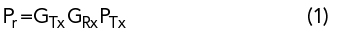
A methodology for determining antenna gain and pattern parameters uses the image created by a conductive plane located at a desired reference position relative to the antenna phase center. The measurement consists of two states. The first is bore-sight perpendicular S11p and the second is free space S11fs. The original work was derived by Edward Purcell.1 Later, Lee and Baddour2 refined the derivation to include a finite mismatch between the antenna and its feed. The method they used involved taking several measurements over distance and performing a best fit line; reflection phase was not considered. Now that modern vector network analyzers (VNAs) can include phase, accuracy is enhanced and the separation is fixed. In addition to antenna under test (AUT) gain, phase can also be calculated such that a full 2-port [S] matrix can be determined.
It is well established that boundary conditions on metallic surfaces require Et = 0. An incident electric field is made zero on the surface by setting up currents equal in amplitude but with opposite phase (see Figure 1). The induced currents are equivalent to the inverted image on the opposite side of the conductor surface and reflect off the surface with the same pattern as the incident wave.1 Equivalently, the field incident on a perfect conductor generates a conjugate field at the surface to maintain the tangential boundary condition Et = 0, which generates an image at the same distance on the opposite side.
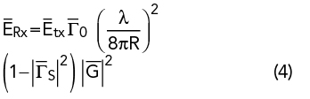
The original work began with the Friis Equation3
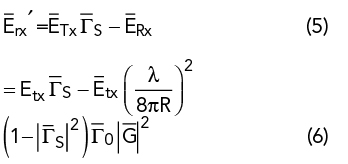
The reflected wave undergoes the same path loss so that the reflection coefficient at the source is

where all variables are linear vectors. R is multiplied by 2 to include the round trip and Γ0 is the reflective surface. If the source reflection is Γs, then the transmit field is

and the field received at the source is
It is assumed G and path loss are linear vectors. The ERx vector linearly combines with the source mismatch so that
The ratio  forms the match vector due to the received reflection. While Equation (4) is a primary reflection, the higher order reflections are ignored imposing the condition |GPL| << 1.
Solving Equation (6) for gain2 gives
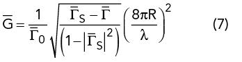
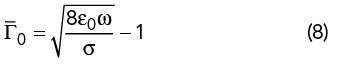
It should be mentioned that all reflection quantities are vectors or Equation (7) will not be accurate.4 The vector difference between the source and measurement reflection yields the AUT gain and phase referenced from the AUT connector and phase center. Equation (7) includes the conductive surface conductivity σ. The surface reflection is given by
For high conductivity, Γ0→-1.
For our measurements the conductive surface is aluminum with σ = 3.5e7 S/M and Equation (8) yields

Where f is in GHz.
At 10 GHz, Γ0 = -0.9996 or 0.003 dB.
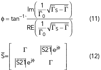
Equation (7) has a phase component determined by  .
.
Equation (8) demonstrates that the sheet reflection loss is negligible as would be the angle deviation from 180 degrees so the AUT phase is entirely determined by the difference between the source reflection and the measured reflection. The resulting gain is
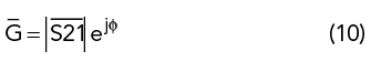
where