Huang et al. used a DGS in a SIW bandpass filter for improved stopband performance.49 Wei et al.50 described an ultrawide band bandpass filter with a DGS comprising a pair of cascaded interdigital hairpin resonators and a semicircular DGS pair (see Figure 9). The cutoff frequency depends on the radius, R1. R1 and cutoff frequency are inversely proportional. By tuning R1 and the gap, W1, the passband of the filter is widened along with wide upper stop band.

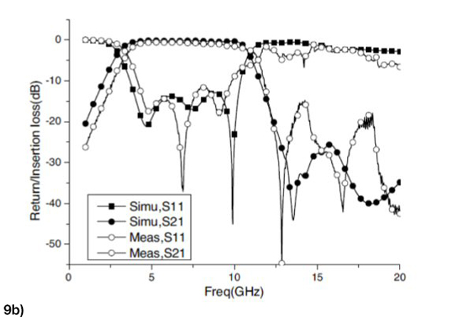
Figure 9 UWB BPF Configuration (a) and its frequency response (b).50
Since all DGSs are etched in the bottom plane, they are not easy to integrate with other components. Hence, some are etched in the transmission line planes of coplanar waveguide and substrate integrated waveguide.51-53 Huang et al.54 developed a SIW BPF using a novel DGS for X-Band applications. They designed three cascaded SIW-DGS cells with the DGSs etched on the top plane. Two CPW-SIW transitions were used for the input /output ports (see Figure 10). The filter had a center frequency of 9 GHz with a fractional bandwidth of 32 percent and insertion loss of about 0.81 dB. It found application in broadband communications.


Figure 10 Three stage cascaded SIW-DGS filter top layer (a) and its filter response (b).54
To reduce SIW filter size, various techniques such as folded SIW filters,55-58 combline SIW filters,59,60 slow wave techniques61 and half mode SIW (HMSIW)62-64 have been used. HMSIW has been used in a number of applications.64-66
Huang et al.67 used a novel HMSIW DGS cell and its embedded form to develop a three-pole cascaded bandpass filter (see Figure 11). Half mode SIW reduced the filter size. The DGS was embedded in the top of the HMSIW. Tuning was achieved by adjusting the spacing between the DGS’s. The filter had a center frequency of 8.8 GHz, a frequency bandwidth (FBW) of 29 percent and insertion loss of 0.91 to 1.14 dB. The overall size was about 27 x 7.5 mm2, which was very compact compared with its conventional counterpart.

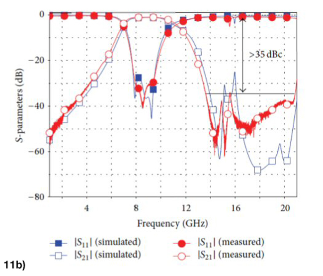
Figure 11 HMSIW DGS filter configuration (a) and its scattering parameters (b).67
SIW FILTERS LOADED WITH METAMATERIALS
Based on the split ring resonator, the complementary split ring resonator (CSRR) was developed in 2004.68 Its characteristics are described by Dong et al.69 An interesting way to reduce the size of a SIW filter is to load a CSRR with the SIW structure.69-73 Many researchers exploited this approach to develop reduced size passive components.74-76 Gao et al.77 combined a complementary spiral resonator (CSR) along with CSRR in SIW to develop a dual band filter (see Figure 12).


Figure 12 Configuration of a dual band SIW filter (a) and its filter response (b).77
In this structure the CSRR produces the first passband and CSRs produce the second passband. Embedding CSRs along with the CSRR not only made the structure compact but it led to an increase in resonant strength, resulting in a positive interaction. The dual band filter was 17 x 18 mm2 with center frequencies of 4.32 GHz and 5.52 GHz and fractional bandwidths of 5.76 and 4.98 percent, respectively. Yin and Lin77 modified a dual CSRR with a Z-shaped slot loaded on the SIW structure to produce dual pass bands (see Figure 13). The Z-shaped slot enhanced coupling, broadening the passband and improving flatness. The first band had a 1.94 GHz center frequency and a bandwidth of 0.28 GHz. The second band had a 4.85 GHz center frequency and a bandwidth of 0.13 GHz.


Figure 13 Filter configuration (a) and frequency response (b).78
Fractals are magnetic dipoles that support backward wave propagation.79,80 Hamzah et al.81 described a three iteration H shaped fractal slot SIW bandpass filter for C-Band applications (see Figure 14). A fractal is defined as a group of scaled replicas of the basic form. The space filling property of fractal can be utilized for miniaturization of microwave components. By tuning the fractal slots, out-of-band rejection is improved. The authors developed one stage, three stage and five stage H shaped fractal SIW BPFs with low insertion loss, high selectivity and small size.
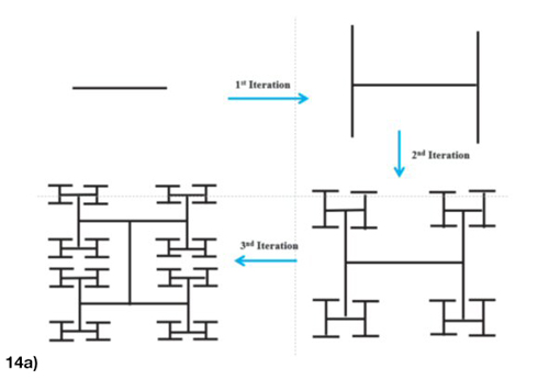

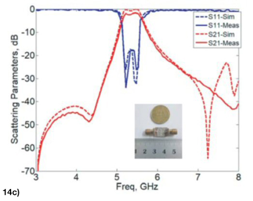
Figure 14 H shaped fractal curve generation (a), one stage H shaped fractal SIW BPF (b) and frequency response (c).81
A fractal open complementary split ring resonator (FOCSRR) was used to design a SIW bandpass filter that operates on the principle of evanescent modes.82 Because the electrical size of the FOCSRR is larger, this results in miniaturization of the SIW bandpass filter. A size reduction of about 75.5 percent was achieved compared with the SIW-OCSRR filter.
Zhang et al.83 designed a SIW filter with a pair of reversely arranged square CSRRs implanted. It had an insertion loss of about 3.5 dB and a FBW of 5.5 percent at 5.15 GHz.
A compact filter using OCSRR and an open stub obtained higher rejection by making the inner ring thickness much greater than that of the outer ring.84
Kumar and Karthikeyan85 used sub-wavelength resonators (OCSRRs) along with two open λg/4 stubs. As the gap between the two split rings increased, coupling capacitance decreased, which in turn increased the resonant frequency of the filter and resulted in good passband characteristics.
TUNABLE SIW FILTERS
Tunable filters play an important role in radio and radar systems to eliminate interference and enhance dynamic range. Microstrip and coplanar waveguide filters with reconfigurable capability have been developed, but with poor quality factors.86-88 SIW reconfigurable filters are attractive alternatives due to their high quality factors and low loss. Tuning was first proposed by inserting vertical capacitive posts, within the SIW cavities.89 Sekar et al.90 designed a novel reconfigurable SIW filter using P-I-N diode elements on a three layer RT Duroid substrate (see Figure 15) for a 25 percent tuning bandwidth. RF MEMS could also be used as switching elements.

Figure 15 SIW filter top view.90
Using a combline resonator,91 a tunable combline SIW cavity loaded with a GaAs varactor was proposed by Sirci et al.92 A two pole tuning filter was also demonstrated.93
Iqbal et al.94 developed two higher order SIW filters by connecting two cavities perpendicular and parallel through the coupling slots. Varactor diodes were used for tuning.
SIW COMPONENTS AND NEW MATERIALS
SIW filters are finding new applications in wearable systems.95,96 SIW circuits have been constructed on paper substrates.97-99 Moro et al.98 used an inkjet printer to deposit silver for SIW top and bottom layers. Another approach used aluminum foils to produce the top and bottom sides of the SIW structure with vias realized using conductive paste (see Figure 16).99
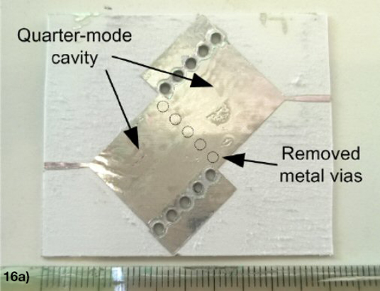
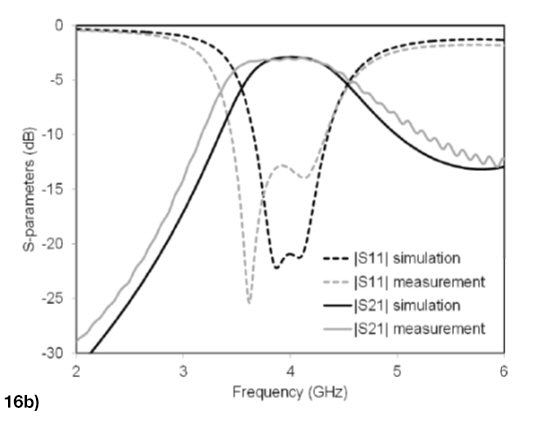
Figure 16 Quarter mode SIW filter (a) and its response (b).99
Moro et al.96 designed, developed and tested a new variety of SIW components on textile fabrics. They designed a folded textile SIW filter operating at 2.45 GHz and a folded SIW cavity backed patch antenna. Wearable electronic goods are becoming more popular.100 SIW structures on the basis of 3D printing have been exploited in the past few years.101-103 Moscato et al.104 employed fused deposition modeling where different material densities from 10 to 100 percent can be printed to control dielectric permittivity and loss tangent.
CONCLUSIONS
Recent developments in the microwave and mmWave filters based on SIW technology reported in the available literature highlights tuning mechanisms, design issues and the integration of SIW components with other transmission line technologies such as microstrip and CPW. SIW filters exhibit many features that can be useful in modern communication system design.
ACKNOWLEDGMENTS
The authors would like to thank the Council of Scientific & Industrial Research, India, a premier national R & D organization for providing financial support for this work.
