
Online Spotlight: A Survey of Substrate Integrated Waveguide Bandpass Filter Development
Substrate integrated waveguide (SIW) is a bridge between planar and non-planar transmission lines. It inherits the merits of both metallic waveguides and planar structures. Non-planar rectangular or circular waveguide can handle high power and provide high selectivity but weighs more and is relatively expensive, where planar transmission line is light weight and producible using low-cost mass production techniques. It cannot, however, withstand high power and generally has higher losses. SIW filters, such as cross coupled filters, defected ground structure (DGS) based filters, metamaterial-based filters, tunable filters and filters on new materials are reviewed along with bandwidth enhancement, size reduction and selectivity improvement.
The electromagnetic spectrum is heavily crowded with wireless signal frequencies. Microwave and mmWave filters are in high demand to enable the reception of desired signals or reject unwanted ones. Bandpass filters are the most popular type for most common applications such as communication systems. They are also the most challenging to design and construct.
An RF filter designer must balance conflicting requirements. For example, achieving high selectivity demands more resonators; but this results in increased insertion loss, which is proportional to the number of resonators. The design parameters of a filter include insertion loss, return loss, group delay, unloaded quality factor, loaded quality factor, external quality factor, cost and skirt selectivity. An RF engineer must balance performance parameters to develop an optimum filter, however, the biggest tradeoff is between performance requirements and cost.
The loss mechanism is another important consideration. Along with the physical and electrical parameters, it depends on the filter’s resonant mode behavior. A particular resonance behavior is associated with the electric and magnetic field distribution of that mode, which in turn is related to the loss mechanism. A resonator can support numerous resonant modes. The excitation mechanism, filter structure and resonant frequency determine the number of modes. Multimode resonators play an important role in determining filter size and insertion loss.
The development of a filter depends on the selection of a suitable transmission line or waveguide technology. A planar microstrip filter weighs less than a waveguide filter, but its quality factor is poor. A non-planar rectangular waveguide filter has an excellent quality factor and handles greater power but is heavier and occupies a larger volume. A fusion of these two technologies by K. Wu in 2001 led to the development of substrate integrated waveguide technology.¹ SIW is popular due to its high quality factor, high-power handling capability, low-cost and low loss.
SIW CONCEPT
SIW is a planar waveguide that can be fabricated using printed circuit board or low temperature cofired ceramic (LTCC) technologies. It is constructed by inserting two rows of metallic via posts into a dielectric substrate with a top and bottom metal lining (see Figure 1).1

Figure 1 SIW configuration.2
The SIW structure supports only the transverse electric mode of propagation.2 The propagation characteristics of the SIW TEn0 mode is like that of the rectangular waveguide TEn0 mode. Absence of a transverse magnetic mode makes SIW an appropriate choice for the design of bandpass filters. The characteristics of SIW are thoroughly discussed by Xu and Wu,2 and by Deslandes and Wu.3 A review of SIW is provided by Kumar and Raghavan.4
The frequency zone of interest for the TE10 mode is3

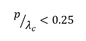
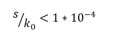

where k0 is the wave number in free space.
Equation (1) states that the period length, p, should be larger than the via diameter, d. Equation (2) must be satisfied to avoid band gap effect. Equation (3) ensures that leakage losses can be neglected. For mechanical rigidity, Equation (4) must be satisfied. Figure 2 shows the zone of interest for SIW in the plane of p/λc and d/λc.

Figure 2 Zone of interest for SIW.3
Rectangular waveguide and SIW parameters are related by5

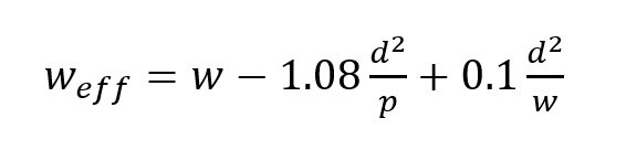
where w is the SIW actual width, weff is its effective width, d is the diameter of the post and p is the pitch.
A more accurate relationship is given by2
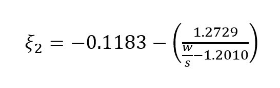
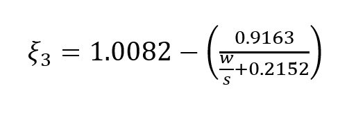
The method of lines provides another empirical relationship6
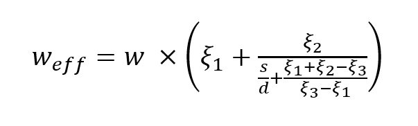
where

Soundarya and Gunavathi analyzed SIW impedance and phase constants.7
SIW TRANSITIONS
Attention must be paid to interconnecting SIW with other planar circuits. The proper excitation of SIW components depends on the quality of these interconnections, or transitions. The basic interconnection of microstrip to SIW is tapering.8,9 Good return loss can be achieved using this type of transition (see Figure 3).
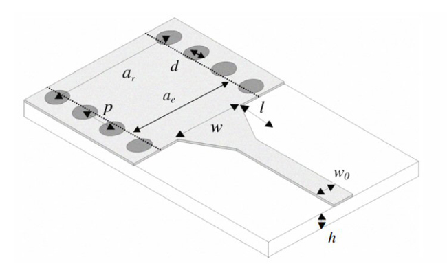
Figure 3 Microstrip to SIW transition.8
Yang et al.10 described an open-circuited transition between a microstrip line and SIW on an LTCC substrate in which energy was transferred to the waveguide through a via probe from the microstrip line. Abdolhamidi et al.11 developed a single-layer DC-decoupled SIW-to-microstrip transition using an interdigital configuration. Instead of a taper, an exponential transition from microstrip to SIW was developed by Sotoodeh et al.12 Transitions from SIW to other transmission lines such as co-axial lines and coplanar waveguide were summarized by Mallick et al.13 Another multi layered transition from SIW to Empty SIW (ESIW) was also proposed.14 Kordiboroujeni and Bornemann15 described a microstrip to SIW transition where two additional vias were implemented in the regular taper to provide excellent results. A new design formula was also proposed by the authors.
SIW RESONATOR
SIW has been used for the design of filters from Gigahetrz to Terahertz. The essential structure of any filter is the resonator. The unloaded quality factor (Qu) depends on the selection of transmission line technology.16 Figure 4 visualizes the relationship between insertion loss, volume and cost of various RF resonators.

Figure 4 Comparative loss, size and cost of various resonators.16,17
For a given resonator, different excitations may lead to different modes, which provide different unloaded quality factors. Figure 5 shows different SIW cavity resonator excitation techniques. Center coupling provides the highest Qu.

Figure 5 Different SIW resonator coupling methods.18
Qu can be obtained from the S-parameters by19,20
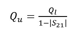
where S21 is the transmission coefficient and Ql is loaded quality factor, which is given as
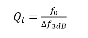
where f0 is the center frequency and f3dB is the 3 dB bandwidth of the filter.
Different classes of SIW filters and their transitions were summarized by Bozzi et al.21 In 2003, D. Deslandes and Ke Wu developed the first SIW filter by integrating planar circuits and waveguide filters.22 A PI network modeled the inductive posts. Post dimeters were calculated with theory proposed by Marcuvitz.23 The PI network was converted into an equivalent K inverter.24 Direct coupled waveguide resonators are compatible with this SIW technique.25-36 This design exhibits a standard Chebyshev response.
SIW CROSS COUPLED FILTERS
An overview of cross coupling was summarized by J.B.Thomas.37 High filter selectivity depends on the location of the finite transmission zeros (FTZs). One way of producing FTZs is to use the cross coupling concept which provides multiple paths for the signal to flow. Whenever two different signal paths have same magnitude but opposite phase, they cancel each other and an FTZ is generated on the imaginary axis of the complex frequency plane. Chen and Wu38 developed a cross coupled filter with stronger negative coupling between resonators 1 and 4 as shown in Figure 6. Positive coupling exists between resonators 1 and 2,2 and 3 and 3 and 4. Magnetic post wall irises provided positive coupling; and, a structure made up of a magnetic coupling iris and a microstrip line with a pair of metallized via-holes provided negative coupling. They developed two K-Band cross coupled SIW bandpass filters, without and with source-load coupling, having a center frequency of 20.5 GHz and respective bandwidths of 700 and 800 MHz.

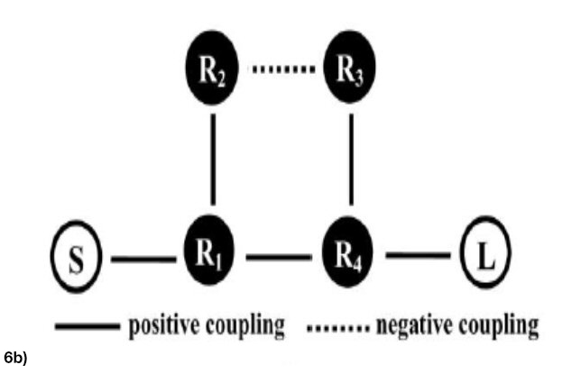

Figure 6 K-Band SIW cross coupled filter without source-load coupling: geometric configuration (a), topology (b) and filter response (c).37
Chen and Wu39 demonstrated a Ka-Band asymmetric response bandpass filter. They used a higher order resonant mode (TE102) to attain negative coupling. The filter had a center frequency of 35 GHz with a 1.3 GHz bandwidth. Conductor backed coplanar waveguide (CBCPW) was used to excite the filter.
Compared to the conventional Chebyshev response, quasi elliptic and elliptic filters have sharp skirt selectivity. Chen et al.40 exploited this property.
An SIW transverse bandpass filter with a mutated doublet was proposed by Li et al.41 It contained two resonators not directly coupled to each other; instead, the source and load were coupled directly to produce two transmission zeros resulting in high skirt selectivity.
SIW FILTERS WITH DGS
Any geometrical slot implanted in the ground plane is called a DGS.42,43 It can be either a unit cell or periodic (see Figure 7).


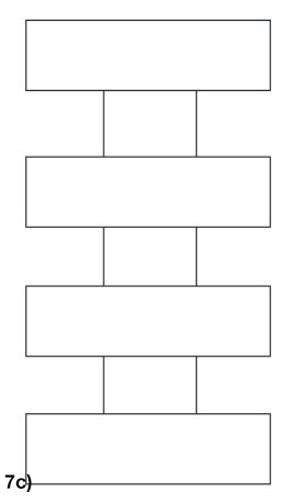
Figure 7 Unit cell – Dumbbell DGS (a), horizontally periodic DGS (b) and vertically periodic DGS (c).43
The DGS is included in the ground extension along transmission line (microstrip, coplanar waveguide or CBCPW).44-48 The defects on the ground plane disturb the current distribution of the ground plane; which, in turn, affects the current distribution on the transmission line. This is because the ground plane defect changes the effective capacitance and inductance of the transmission line. A photonic band gap occupies a larger area, where the DGS is compact. It is also easy to design and fabricate. Various other DGS shapes are shown in Figure 8. These configurations offer higher slow wave factors, larger external quality factors and a wider stop bands with deeper rejection.

Figure 8 Different DGS configurations: spiral head (a), arrow head slot (b), “H” shape slots (c), square open loop with a slot in middle section (d), open loop dumbbell (e) and inter digital (f).42
Huang et al. used a DGS in a SIW bandpass filter for improved stopband performance.49 Wei et al.50 described an ultrawide band bandpass filter with a DGS comprising a pair of cascaded interdigital hairpin resonators and a semicircular DGS pair (see Figure 9). The cutoff frequency depends on the radius, R1. R1 and cutoff frequency are inversely proportional. By tuning R1 and the gap, W1, the passband of the filter is widened along with wide upper stop band.

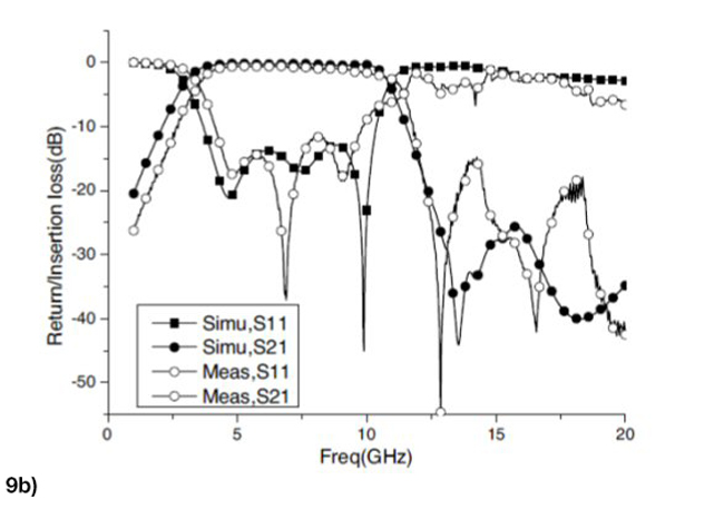
Figure 9 UWB BPF Configuration (a) and its frequency response (b).50
Since all DGSs are etched in the bottom plane, they are not easy to integrate with other components. Hence, some are etched in the transmission line planes of coplanar waveguide and substrate integrated waveguide.51-53 Huang et al.54 developed a SIW BPF using a novel DGS for X-Band applications. They designed three cascaded SIW-DGS cells with the DGSs etched on the top plane. Two CPW-SIW transitions were used for the input /output ports (see Figure 10). The filter had a center frequency of 9 GHz with a fractional bandwidth of 32 percent and insertion loss of about 0.81 dB. It found application in broadband communications.


Figure 10 Three stage cascaded SIW-DGS filter top layer (a) and its filter response (b).54
To reduce SIW filter size, various techniques such as folded SIW filters,55-58 combline SIW filters,59,60 slow wave techniques61 and half mode SIW (HMSIW)62-64 have been used. HMSIW has been used in a number of applications.64-66
Huang et al.67 used a novel HMSIW DGS cell and its embedded form to develop a three-pole cascaded bandpass filter (see Figure 11). Half mode SIW reduced the filter size. The DGS was embedded in the top of the HMSIW. Tuning was achieved by adjusting the spacing between the DGS’s. The filter had a center frequency of 8.8 GHz, a frequency bandwidth (FBW) of 29 percent and insertion loss of 0.91 to 1.14 dB. The overall size was about 27 x 7.5 mm2, which was very compact compared with its conventional counterpart.

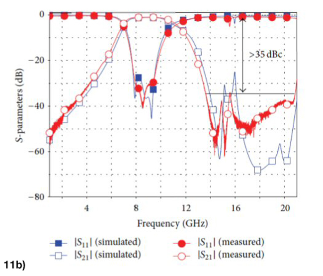
Figure 11 HMSIW DGS filter configuration (a) and its scattering parameters (b).67
SIW FILTERS LOADED WITH METAMATERIALS
Based on the split ring resonator, the complementary split ring resonator (CSRR) was developed in 2004.68 Its characteristics are described by Dong et al.69 An interesting way to reduce the size of a SIW filter is to load a CSRR with the SIW structure.69-73 Many researchers exploited this approach to develop reduced size passive components.74-76 Gao et al.77 combined a complementary spiral resonator (CSR) along with CSRR in SIW to develop a dual band filter (see Figure 12).


Figure 12 Configuration of a dual band SIW filter (a) and its filter response (b).77
In this structure the CSRR produces the first passband and CSRs produce the second passband. Embedding CSRs along with the CSRR not only made the structure compact but it led to an increase in resonant strength, resulting in a positive interaction. The dual band filter was 17 x 18 mm2 with center frequencies of 4.32 GHz and 5.52 GHz and fractional bandwidths of 5.76 and 4.98 percent, respectively. Yin and Lin77 modified a dual CSRR with a Z-shaped slot loaded on the SIW structure to produce dual pass bands (see Figure 13). The Z-shaped slot enhanced coupling, broadening the passband and improving flatness. The first band had a 1.94 GHz center frequency and a bandwidth of 0.28 GHz. The second band had a 4.85 GHz center frequency and a bandwidth of 0.13 GHz.


Figure 13 Filter configuration (a) and frequency response (b).78
Fractals are magnetic dipoles that support backward wave propagation.79,80 Hamzah et al.81 described a three iteration H shaped fractal slot SIW bandpass filter for C-Band applications (see Figure 14). A fractal is defined as a group of scaled replicas of the basic form. The space filling property of fractal can be utilized for miniaturization of microwave components. By tuning the fractal slots, out-of-band rejection is improved. The authors developed one stage, three stage and five stage H shaped fractal SIW BPFs with low insertion loss, high selectivity and small size.
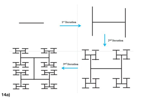

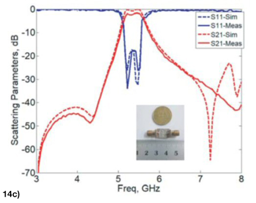
Figure 14 H shaped fractal curve generation (a), one stage H shaped fractal SIW BPF (b) and frequency response (c).81
A fractal open complementary split ring resonator (FOCSRR) was used to design a SIW bandpass filter that operates on the principle of evanescent modes.82 Because the electrical size of the FOCSRR is larger, this results in miniaturization of the SIW bandpass filter. A size reduction of about 75.5 percent was achieved compared with the SIW-OCSRR filter.
Zhang et al.83 designed a SIW filter with a pair of reversely arranged square CSRRs implanted. It had an insertion loss of about 3.5 dB and a FBW of 5.5 percent at 5.15 GHz.
A compact filter using OCSRR and an open stub obtained higher rejection by making the inner ring thickness much greater than that of the outer ring.84
Kumar and Karthikeyan85 used sub-wavelength resonators (OCSRRs) along with two open λg/4 stubs. As the gap between the two split rings increased, coupling capacitance decreased, which in turn increased the resonant frequency of the filter and resulted in good passband characteristics.
TUNABLE SIW FILTERS
Tunable filters play an important role in radio and radar systems to eliminate interference and enhance dynamic range. Microstrip and coplanar waveguide filters with reconfigurable capability have been developed, but with poor quality factors.86-88 SIW reconfigurable filters are attractive alternatives due to their high quality factors and low loss. Tuning was first proposed by inserting vertical capacitive posts, within the SIW cavities.89 Sekar et al.90 designed a novel reconfigurable SIW filter using P-I-N diode elements on a three layer RT Duroid substrate (see Figure 15) for a 25 percent tuning bandwidth. RF MEMS could also be used as switching elements.

Figure 15 SIW filter top view.90
Using a combline resonator,91 a tunable combline SIW cavity loaded with a GaAs varactor was proposed by Sirci et al.92 A two pole tuning filter was also demonstrated.93
Iqbal et al.94 developed two higher order SIW filters by connecting two cavities perpendicular and parallel through the coupling slots. Varactor diodes were used for tuning.
SIW COMPONENTS AND NEW MATERIALS
SIW filters are finding new applications in wearable systems.95,96 SIW circuits have been constructed on paper substrates.97-99 Moro et al.98 used an inkjet printer to deposit silver for SIW top and bottom layers. Another approach used aluminum foils to produce the top and bottom sides of the SIW structure with vias realized using conductive paste (see Figure 16).99
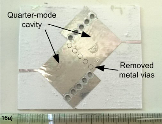
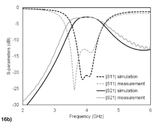
Figure 16 Quarter mode SIW filter (a) and its response (b).99
Moro et al.96 designed, developed and tested a new variety of SIW components on textile fabrics. They designed a folded textile SIW filter operating at 2.45 GHz and a folded SIW cavity backed patch antenna. Wearable electronic goods are becoming more popular.100 SIW structures on the basis of 3D printing have been exploited in the past few years.101-103 Moscato et al.104 employed fused deposition modeling where different material densities from 10 to 100 percent can be printed to control dielectric permittivity and loss tangent.
CONCLUSIONS
Recent developments in the microwave and mmWave filters based on SIW technology reported in the available literature highlights tuning mechanisms, design issues and the integration of SIW components with other transmission line technologies such as microstrip and CPW. SIW filters exhibit many features that can be useful in modern communication system design.
ACKNOWLEDGMENTS
The authors would like to thank the Council of Scientific & Industrial Research, India, a premier national R & D organization for providing financial support for this work.
References
1. K. Wu, “Integration and Interconnect Techniques of Planar and Nonplanar Structures for Microwave and Millimeter-Wave Circuits, Current Status and Future Trends,” Proceedings of the Asia Pacific Microwave Conference, December 2001, pp. 411-416.
2. F. Xu and K. Wu, “Guided-Wave and Leakage Characteristics of Substrate Integrated Waveguide,” IEEE Transactions on Microwave Theory and Techniques, Vol. 53, No. 1, January 2005, pp. 66–73.
3. D. Deslandes and K. Wu, “Accurate Modeling, Wave Mechanisms, and Design Considerations of a Substrate Integrated Waveguide,” IEEE Transactions on Microwave Theory and Techniques, Vol. 54, No. 6, June 2006, pp. 2516-2526.
4. A. Kumar and S. Raghavan, “A Review: Substrate Integrated Waveguide Antennas and Arrays,” Journal of Telecommunication, Electronic and Computer Engineering, Vol. 8, No. 5, May-August 2016, pp. 95-104.
5. Y. Cassivi, L. Perregrini, P. Arcioni, M. Bressan, K. Wu and G. Conciauro, “Dispersion Characteristics of Substrate Integrated Rectangular Waveguide,” IEEE Microwave and Wireless Components Letters, Vol. 12, No. 9, September 2002, pp. 333-335.
6. F. T. Ladani, S. Jam and R. Safian, “Comment on Analytical Equivalence Between Substrate-Integrated Waveguide and Rectangular Waveguide,” IET Microwaves, Antennas and Propagation, Vol. 7, No. 1, 2013, pp. 24-25.
7. G. Soundarya and N. Gunavathi, “Low Loss and High-Power Substrate Integrated Waveguide for High Speed Circuits,” Microwave Journal, Vol. 63, No. 4, April 2020.
8. D. Deslandes and K. Wu, “Integrated Microstrip and Rectangular Waveguide in Planar Form,” IEEE Microwave and Wireless Components Letters, Vol. 11, No. 2, February 2001, pp. 68-70.
9. D. Deslandes, “Design Equations for Tapered Microstrip-to-Substrate Integrated Waveguide Transitions,” IEEE MTT-S International Microwave Symposium, May 2010.
10. T. -H. Yang, C. -F. Chen, T. -Y. Huang, C. -L. Wang and R. -B. Wu, “A 60 GHz LTCC Transition Between Microstrip Line and Substrate Integrated Waveguide,” Asia-Pacific Microwave Conference, December 2005.
11. M. Abdolhamidi, A. Enayati, M. Shahabadi and R. Faraji-Dana, “Wideband Single-Layer DC-Decoupled Substrate Integrated Waveguide (SIW) - to - Microstrip Transition Using an Interdigital Configuration,” Asia Pacific Microwave Conference, December 2007.
12. Z. Sotoodeh, B. Biglarbegian, F. H. Kashani and H. Ameri, “A Novel Bandpass Waveguide Filter Structure on SIW Technology,” Progress in Electromagnetics Research Letters, Vol. 2, 2008, pp. 141–148.
13. S. G. Mallick, G. A. Kumar, S. Chatterjee, B. Biswas and D. R. Poddar, “Transitions from SIW to Various Transmission Lines for Substrate Integrated Circuits,” Asia-Pacific Radio Science Conference, March 2019.
14. S. G. Mallick, B. Biswas, S. Chatterjee, G. Arun Kumar and D. R. Poddar, “A Multilayered Transition between SIW and ESIW,” IEEE Calcutta Conference, June 2020.
15. Z. Kordiboroujeni and J. Bornemann, “New Wideband Transition from Microstrip Line to Substrate Integrated Waveguide,” IEEE Transactions on Microwave Theory and Techniques, Vol. 62, No. 12, December 2014, pp. 2983-2989.
16. R. R. Mansour, “High-Q Tunable Dielectric Resonator Filters,” IEEE Microwave Magazine, Vol. 10, No. 6, October 2009, pp. 84-98.
17. S. J. Fiedziuszko and S. Holme, “Dielectric Resonators Raise Your High-Q,” IEEE Microwave Magazine, Vol. 2, No. 3, September 2001, pp. 50-60.
18. Y. Cassivi, L. Perregrini, K. Wu and G. Conciauro, “Low-Cost and High-Q Millimeter-Wave Resonator Using Substrate Integrated Waveguide Technique,” European Microwave Conference, September 2002.
19. R. S. Kwok and J. F. Liang, “Characterization of High-Q Resonators for Microwave-Filter Applications,” IEEE Transactions on Microwave Theory and Techniques, Vol. 47, No. 1, January 1999, pp. 111–114.
20. J. Hong and M. J. Lancaster, Microstrip Filters for RF / Microwave Applications, 2001, John Wiley & Sons.
21. M. Bozzi, A. Georgiadis and K. Wu, “Review of Substrate-Integrated Waveguide Circuits and Antennas,” IET Microwaves, Antennas and Propagation, Vol. 5, No. 8, July 2011, pp. 909–920.
22. D. Deslandes and K. Wu, “Single-Substrate Integration Technique of Planar Circuits and Waveguide Filters,” IEEE Transactions on Microwave Theory and Techniques, Vol. 51, No. 2, February 2003, pp. 593-596.
23. N. Marcuvitz, Waveguide Handbook, IET, 1986.
24. G. Matthaei, L. Young and E. M. T. Jones, Microwave Filters, Impedance-Matching Networks and Coupling Structures, McGraw Hill, 1964.
25. Y. L. Zhang, W. Hong, K. Wu, J. X. Chen and H. J. Tang, “Novel Substrate Integrated Waveguide Cavity Filter with Defected Ground Structure,” IEEE Transactions on Microwave Theory and Techniques, Vol. 53, No. 4, April 2005, pp. 1280–1287, 2005.
26. H. Leblond, J. F. Villemazet, J. L. Cazaux, D. Pacaud, J. J. Herren, L. Rigaudeau, L. Lapierre, D. Baillargeat, P. Blondy, S. Bila, S. Verdeyme, C. Delage, C. Quendo, J. F. Favennec, B. Potelon, E. Rius, F. Seyfert and S. Pacchini, “When New Needs for Satellite Payloads Meet with New Filters, Architecture and Technologies,” European Microwave Integrated Circuits Conference, September 2009.
27. M. Salehi and E. Mehrshahi, “A Closed-Form Formula for Dispersion Characteristics of Fundamental SIW Mode,” IEEE Microwave and Wireless Components Letters, Vol. 21, No. 1, January 2011, pp. 4-6.
28. D. Deslandes and K. Wu, “Millimeterwave Substrate Integrated Waveguide Filters,” Canadian Conference on Electrical and Computer Engineering, May 2003.
29. Z. C. Hao, W. Hong, J. X. Chen, X. P. Chen and K. Wu, “Planar Diplexer for Microwave Integrated Circuits,” IEE Proceedings on Microwaves, Antennas and Propagation, Vol. 152, No. 6, December 2005, pp. 455-459.
30. T. S. Yun, H. Nam, K. B. Kim and J. C. Lee, “Iris Waveguide Bandpass Filter Using Substrate Integrated Waveguide (SIW) for Satellite Communication,” Asia-Pacific Microwave Conference Proceedings, 2005.
31. C. T. Bui, P. Lorenz, M. Saglam, W. Kraemer and R. H. Jansen, “Investigation of Symmetry Influence in Substrate Integrated Waveguide (SIW) Band-Pass Filters Using Symmetric Inductive Posts,” European Microwave Conference, October 2008.
32. X. -P. Chen and Ke Wu, “Accurate and Efficient Design Approach of Substrate Integrated Waveguide Filter Using Numerical TRL Calibration Technique,” IEEE MTT-S International Microwave Symposium, June 2008.
33. F. Mira, A. A. San Blast, V. E. Boria and B. Gimeno, “Fast and Accurate Analysis and Design of Substrate Integrated Waveguide (SIW) Filters,” European Microwave Conference, October 2007.
34. F. Mira, A. A. San Blas, S. Cogollos, V. E. Boria and B. Gimeno, “Computer-Aided Design of Substrate Integrated Waveguide Filters for Microwave and Millimeter-Wave Applications,” European Microwave Conference, October 2009.
35. F. Mira, M. Bozzi, F. Giuppi, L. Perregrini and A. Georgiadis, “Calibrated Space-Mapping Approach for the Design of SIW Filters,” European Microwave Conference, September 2010.
36. F. Mira, M. Bozzi, F. Giuppi, L. Perregrini and A. Georgiadis, “Efficient Design of SIW Filters by Using Equivalent Circuit Models and Calibrated Space-Mapping Optimization,” International Journal of RF and Microwave Computer Aided Engineering, Vol. 20, No. 6, October 2010, pp. 689-698.
37. J. B. Thomas, “Cross-Coupling in Coaxial Cavity Filters - A Tutorial Overview,” IEEE Transactions on Microwave Theory and Techniques, Vol. 51, No. 4, April 2003, pp. 1368-1376.
38. X. P. Chen and K. Wu, “Substrate Integrated Waveguide Cross-Coupled Filter with Negative Coupling Structure,” IEEE Transactions on Microwave Theory and Techniques, Vol. 56, No. 1, January 2008, pp. 142-149.
39. X. P. Chen and K. Wu, “Self-Packaged Millimeter-Wave Substrate Integrated Waveguide Filter with Asymmetric Frequency Response,” IEEE Transactions on Components, Packaging and Manufacturing Technology, Vol. 2, No. 5, May 2012, pp. 775–782, 2012.
40. X. Chen, W. Hong, J. Chen and K. Wu, “Substrate Integrated Waveguide Elliptic Filter with High Mode,” Asia-Pacific Microwave Conference, December 2005.
41. R. Li, X. Tang and F. Xiao, “Design of Substrate Integrated Waveguide Transversal Filter with High Selectivity,” IEEE Microwave and Wireless Components Letters, Vol. 20, No. 6, Jun. 2010, pp. 328-330.
42. L. H. Weng, Y. -C. Guo, X. -W. Shi and X. -Q. Chen, “An Overview on Defected Ground Structure,” Progress in Electromagnetics Research B, Vol. 7, April 2008, pp. 173-189.
43. M. K. Khandelwal, B. K. Kanaujia, and S. Kumar, “Defected Ground Structure: Fundamentals, Analysis, and Applications in Modern Wireless Trends,” International Journal of Antennas and Propagation, February 2017.
44. A. M. E. Safwat, F. Podevin, P. Ferrari and A. Vilcot, “Tunable Bandstop Defected Ground Structure Resonator Using Reconfigurable Dumbbell-Shaped Coplanar Waveguide,” IEEE Transactions on Microwave Theory and Techniques, Vol. 54, No. 9, September 2006, pp. 3559-3564.
45. J. -S. Lim, C. -S. Kim, J. S. Park, D. Ahn and S. Nam, “Design of 10 dB 90° Branch Line Coupler Using Microstrip Line with Defected Ground Structure,” Electronics Letters, Vol. 36, No. 21, October 2000, pp. 1784-1785, Oct. 2000.
46. Y. J. Sung, C. S. Ahn and Y. S. Kim, “Size Reduction and Harmonic Suppression of Rat-Race Hybrid Coupler Using Defected Ground Structure,” IEEE Microwave and Wireless Components Letters, Vol. 14, No. 1, January 2004, pp. 7-9.
47. H. -J. Chen, T. -H. Huang, C. -S. Chang, L. -S. Chen, N. -F. Wang, Y. -H. Wang and Mau-P. Houng “A Novel Cross-Shape DGS Applied to Design Ultra-Wide Stopband Low-Pass Filters,” IEEE Microwave and Wireless Components Letters, Vol. 16, No. 5, May 2006, pp. 252-254.
48. D. Piscaretta, S. W. Ting and K. W. Tam, “Erratum: Microstrip Parallel Coupled-Line Bandpass Filter with Selectivity Improvement Using U-Shaped Defected Ground Structure,” Microwave and Optical Technology Letters, Vol. 50, No. 10, 2008, pp. 911-915.
49. T. Huang, X. Yang, Y. Huang, Z. He and Z. Shao, “An X-Band SIW-DGS Bandpass Filter with Improved Stopband Performance,” IEEE International Conference on Communication Problem-Solving, October 2015.
50. F. Wei, P. Chen, L. Chen and X. W. Shi, “Design of a Compact UWB Bandpass Filter with Defected Ground Structure,” Journal of Electromagnetic Waves and Applications, Vol. 22, No. 13, October 2008, pp. 1783-1790.
51. Z. Shao and M. Fujise, “Bandpass Filter Design Based on LTCC and DGS,” Asia-Pacific Microwave Conference, December 2005.
52. P. -Y. Ke, H. -C. Chiu, F. -H. Huang, H. -L. Kao and Q. Xue, “Characterization of Compact V-Band GaAs CMRC Filter Using Slow Wave CPW Transmission Line Technology,” Progress in Electromagnetics Research B, Vol. 43, January 2012, pp. 355-372.
53. X. -C. Zhang, Z. -Y. Yu and J. Xu, “Novel Band-Pass Substrate Integrated Waveguide (SIW) Filter Based on Complementary Split Ring Resonators (CSRRs),” Progress in Electromagnetics Research, Vol. 72, March 2007, pp. 39-46.
54. Y. Huang, Z. Shao and L. Liu, “A Substrate Integrated Waveguide Bandpass Filter Using Novel Defected Ground Structure Shape,” Progress Electromagnetics Research, Vol. 135, December 2012, pp. 201–213.
55. N. Grigoropoulos, B. Sanz-Izquierdo and P. R. Young, “Substrate Integrated Folded Waveguides (SIFW) and Filters,” IEEE Microwave and Wireless Components Letters, Vol. 15, No. 12, December 2005, pp. 829-831.
56. S. K. Alotaibi and J. -S. Hong, “Novel Substrate Integrated Folded Waveguide Filter,” Microwave Optical Technology Letters, Vol. 50, No. 4, April 2008, pp. 1111-1114.
57. L. -S. Wu, X. -L. Zhou and W. -Y. Yin, “A Novel Multilayer Partial H-Plane Filter Implemented with Folded Substrate Integrated Waveguide (FSIW),” IEEE Microwave and Wireless Components Letters, Vol. 19, No. 8, August 2009, pp. 494-496, Aug. 2009.
58. S. K. Alotaibi and J. S. Hong, “Substrate Integrated Folded-Waveguide Filter with Asymmetrical Frequency Response,” European Microwave Conference, October 2008.
59. J. D. Martinez, S. Sirci, M. Taroncher and V. E. Boria, “Compact CPW-Fed Combline Filter in Substrate Integrated Waveguide Technology,” IEEE Microwave and Wireless Components Letters, Vol. 22, No. 1, January 2012, pp. 7-9.
60. J. D. Martinez, S. Sirci and V. E. Boria, “Compact SIW Filter with Asymmetric Frequency Response for C-Band Wireless Applications,” IEEE International Wireless Symposium, October 2013.
61. A. Parameswaran and S. Raghavan, “Slow Wave Microstrip Line and its Application in Miniaturization,” International Journal of RF and Microwave Computer-Aided Engineering, Vol. 28, No. 5, February 2018, pp. 1-7.
62. L. -S. Wu, X. -L. Zhou, W. -Y. Yin, C. -T. Liu, L. Zhou, J. -F. Mao and H. -L. Peng, “A New Type of Periodically Loaded Half-Mode Substrate Integrated Waveguide and its Applications,” IEEE Transactions on Microwave Theory and Techniques, Vol. 58, No. 4, April 201, pp. 882-893.
63. Y. Cheng, W. Hong and K. Wu, “Half Mode Substrate Integrated Waveguide (HMSIW) Directional Filter,” IEEE Microwave and Wireless Components Letters, Vol. 17, No. 7, July 2007, pp. 504-506.
64. Y. Wang, W. Hong, Y. Dong, B. Liu, H. J. Tang, J. Chen, X. Yin and K. Wu, “Half Mode Substrate Integrated Waveguide (HMSIW) Bandpass Filter,” IEEE Microwave and Wireless Components Letters, Vol. 17, No. 4, April 2007, pp. 265-267.
65. B. Liu, W. Hong, Y. -Q. Wang, Q. -H. Lai and K. Wu, “Half Mode Substrate Integrated Waveguide (HMSIW) 3-dB Coupler,” IEEE Microwave and Wireless Components Letters, Vol. 17, No. 1, January 2007, pp. 22-24.
66. W. Hong, Y. Wang, Q. Lai, H. Tang, X. X. Yin, Y. D. Dong, Y. Zhang and K. Wu, “Half Mode Substrate Integrated Waveguide: A New Guided Wave Structure for Microwave and Millimeter Wave Application,” Joint 31st International Conference on Infrared and Millimeter Waves and 14th International Conference on Terahertz Electronics, September 2006.
67. Y. M. Huang, Z. Shao, Z. He, C. J. You and D. Jiang, “A Bandpass Filter Based on Half Mode Substrate Integrated Waveguide-to-Defected Ground Structure Cells,” International Journal of Antennas and Propagation, Vol. 2015, February 2015.
68 .F. Falcone, T. Lopetegi, J. D. Baena, R. Marqués, F. Martín and M. Sorolla, “Effective Negative-ε Stopband Microstrip Lines Based on Complementary Split Ring Resonators,” IEEE Microwave and Wireless Components Letters, Vol. 14, No. 6, June 2004, pp. 280-282.
69. Y. D. Dong, T. Yang and T. Itoh, “Substrate Integrated Waveguide Loaded by Complementary Split-Ring Resonators and its Applications to Miniaturized Waveguide Filters,” IEEE Transactions on Microwave Theory and Techniques, Vol. 57, No. 1, January 2009, pp. 2211-2223.
70. W. Shen, X. W. Sun, W. Y. Yin, J. F. Mao and Q. F. Wei, “A Novel Single-Cavity Dual Mode Substrate Integrated Waveguide Filter with Non-Resonating Node,” IEEE Microwave and Wireless Components Letters, Vol. 19, No. 6, June 2009, pp. 368-370.
71. Q. L. Zhang, W. Y. Yin, S. He and L. S. Wu, “Compact Substrate Integrated Waveguide (SIW) Bandpass Filter with Complementary Split-Ring Resonators (CSRRs),” IEEE Microwave and Wireless Components Letters, Vol. 20, No. 8, August 2010, pp. 426-428.
72. L. S. Wu, X. L. Zhou, Q. F. Wei and W. Y. Yin, “An Extended Doublet Substrate Integrated Waveguide (SIW) Bandpass Filter with a Complementary Split Ring Resonator (CSRR),” IEEE Microwave and Wireless Components Letters, Vol. 19, No. 12, December 2009, pp. 777-779.
73. Y. Dong and T. Itoh, “Substrate Integrated Waveguide Loaded by Complementary Split-Ring Resonators for Miniaturized Diplexer Design,” IEEE Microwave and Wireless Components Letters, Vol. 21, No. 1, January 2011, pp. 10-12.
74. Y. M. Huang, Z. Shao, W. Jiang, T. Huang and G. Wang, “Half-Mode Substrate Integrated Waveguide Bandpass Filter Loaded with Horizontal-Asymmetrical Stepped-Impedance Complementary split-ring Resonators,” Electronics Letters, Vol. 52, No. 12, June 2016, pp. 1034-1036.
75. Y. M. Huang, Y. Peng, Y. Zhou, H. Jin, S. Leng and G. Wang, “Size-Reduced Dual-Band HMSIW Cavity Filters Loaded with Double-Sided SICSRRs,” Electronics Letters, Vol. 53, No. 10, May 2017, pp. 689-691.
76. S. Xu, K. Ma, F. Meng and K. S. Yeo, “Novel Defected Ground Structure and Two-Side Loading Scheme for Miniaturized Dual-Band SIW Bandpass Filter Designs,” IEEE Microwave and Wireless Components Letters, Vol. 25, No. 4, April 2015, pp. 217-219.
77. H. Y. Gao, Z. X. Tang, X. Cao, Y. Q. Wu and B. Zhang, “Compact Dual-Band SIW Filter with CSRRS and Complementary Spiral Resonators,” Microwave and Optical Technology Letters, Vol. 58, No. 1, January 2016, pp. 1-4.
78. B. Yin and Z. Lin, “A Novel Dual-Band Bandpass SIW Filter Loaded with Modified Dual-CSRRs and Z-shaped Slot,” AEU International Journal of Electronics and Communications, Vol. 121, July 2020.
79. H. Cao, F. Jiang, J. Liu, W. Cai, M. Tang, X. Tan and S. Yang, “A CSRR-fed SIW Cavity-Backed Fractal Patch Antenna for Wireless Energy Harvesting and Communication,” Sensors, Vol. 15, No. 9, September 2015, pp. 21196-21203.
80. M. Danaeian, K. Afrooz and A. Hakimi, “Miniaturization of Substrate Integrated Waveguide Filters Using Novel Compact Metamaterial Unit-Cells Based on SIR Technique,” AEU International Journal of Electronics and Communications, Vol. 84, February 2018, pp. 62-73.
81. A. M. Hamzah, L. Audah and N. Alkhafaji, “H-Shaped Fractal Slots Based Highly Miniaturized Substrate Integrated Waveguide Metamaterial Bandpass Filters for C-Band Applications,” Progress in Electromagnetics Research B, Vol. 86, March 2020, pp. 139-158.
82. M. Danaeian and H. Ghayoumi-Zadeh, “Miniaturized Substrate Integrated Waveguide Filter Using Fractal Open Complementary Split-Ring Resonators,” International Journal of RF and Microwave Computer-Aided Engineering, Vol. 28, No. 5, June 2018.
83. X. Zhang and M. Yu, “A SIW Filter with Square Complementary Split-Ring Resonators (CSRRs),” USNC-URSI Radio Science Meeting (Joint with AP-S Symposium), October 2017.
84. S. S. Karthikeyan and R. S. Kshetrimayum, “Compact, Deep, and Wide Rejection Bandwidth Low-Pass Filter Using Open Complementary Split Ring Resonator,” Microwave and Optical Technology Letters, Vol. 53, No. 4, February 2011, pp. 845-848.
85. K. V. Phani Kumar and S. S. Karthikeyan, “A Compact and High Performance Band-Stop Filter Using Open Complementary Split Ring Resonator,” National Conference on Communications, February 2013.
86. S. X. Zhang, Z. H. Chen, Q. X. Chu and S. Member, “Compact Tunable Balanced Bandpass Filter with Novel Multi-Mode Resonator,” IEEE Microwave and Wireless Components Letters, Vol. 27, No. 1, January 2017, pp. 43-45.
87. H. Y. Tsai, T. Y. Huang and R. B. Wu, “Varactor-Tuned Compact Dual-Mode Tunable Filter with Constant Passband Characteristics,” IEEE Transactions on Components, Packaging and Manufacturing Technology, Vol. 6, No. 9, September 2016, pp. 1399-1407.
88. C. L. Resonator, H. Zhu and A. M. Abbosh, “Tunable Balanced Bandpass Filter With Wide Tuning Range of Center Frequency and Bandwidth Using Compact Coupled-Line Resonator,” IEEE Microwave and Wireless Components Letters, Vol. 26, No. 1, January 2016, pp. 7-9.
89. J. C. Bohórquez, B. Potelon, C. Person, E. Rius, C. Quendo, G. Tanne, C. Quendo, G. Tanne and E. Fourn, “Reconfigurable Planar SIW Cavity Resonator and Filter,” IEEE MTT-S International Microwave Symposium, June 2006.
90. V. Sekar, M. Armendariz and K. Entesari, “A 1.2-1.6-GHz Substrate-Integrated-Waveguide RF MEMS Tunable Filter,” IEEE Transactions on Microwave Theory and Techniques, Vol. 59, No. 4, April 2011, pp. 866-876.
91. J. D. Martínez, M. Taroncher and V. E. Boria, “Capacitively Loaded Resonator for Compact Substrate Integrated Waveguide Filters,” European Microwave Conference, September 2010.
92. S. Sirci, J. D. Martínez, M. Taroncher and V. E Boria “Varactor Loaded Continuously Tunable SIW Resonator for Reconfigurable Filter Design,” European Microwave Conference, December 2011.
93. S. Sirci, J. D. Martínez, M. Taroncher, and V. E. Boria, “Analog Tuning of Compact Varactor-Loaded Combline Filters in Substrate Integrated Waveguide,” European Microwave Conference, October-November 2012.
94. A. Iqbal, A. W. Ahmad, A. Smida, and N. K. Mallat, “Tunable SIW Bandpass Filters with Improved Upper Stopband Performance,” IEEE Transactions on Circuits Systems II: Express Briefs, Vol. 67, No. 7, July 2020, pp. 1194-1198.
95. R. Moro, S. Agneessens, H. Rogier and M. Bozzi, “Wearable Textile Antenna in Substrate Integrated Waveguide Technology,” IET Electronics Letters, Vol. 48, No. 16, August 2012, pp. 985-987.
96. R. Moro, S. Agneessens, H. Rogier, A. Dierck, and M. Bozzi, “Textile Microwave Components in Substrate Integrated Waveguide Technology,” IEEE Transactions on Microwave Theory and Techniques, Vol. 63, No. 2, February 2015, pp. 422-432.
97. S. Kim, B. Cook, T. Le, J. Cooper, H. Lee, V. Lakafosis, R. Vyas, R. Moro, M. Bozzi, A. Georgiadis, A. Collado and M. Tentzeris, “Inkjet-Printed Antennas, Sensors and Circuits on Paper Substrate,” IET Microwaves, Antennas and Propagation, Vol. 7, No. 10, July 2013, pp. 858-868.
98. R. Moro, S. Kim, M. Bozzi and M. Tentzeris, “Inkjet-Printed Paper-Based Substrate-Integrated Waveguide (SIW) Components and Antennas,” International Journal of Microwave and Wireless Technologies, Jun. 2013, Vol. 5, No. 3, June 2013, pp. 197-204.
99. S. Moscato, R. Moro, M. Pasian, M. Bozzi and L. Perrrigrini, “An Innovative Manufacturing Approach for Paper-Based Substrate Integrated Waveguide Components and Antennas,” IET Microwaves, Antennas and Propagation, Vol. 10, No. 3, January 2016, pp. 256-263.
100. C. Hertleer, H. Rogier, L. Vallozzi and L. Van Langenhove, “A Textile Antenna for Off-Body Communication Integrated into Protective Clothing for Firefighters,” IEEE Transactions on Antennas and Propagation, Vol. 57, No. 4, April 2009, pp. 919-925.
101. R. A. Bahr, L. Perregrini, T. Le and M. M. Tentzeris, “Additive Manufacturing of 3D Substrate Integrated Waveguide Components,” IET Electronics Letters, Vol. 51, No. 18, September 2015, pp. 1426-1428.
102. S. Moscato, M. Pasian, M. Bozzi, L. Perregrini, R. Bahr, T. Le and M. M. Tentzeris, “Exploiting 3D Printed Substrate for Microfluidic SIW Sensor,” European Microwave Conference, December 2015.
103. E. Massoni, L. Silvestri, G. Alaimo, S. Marconi, M. Bozzi, L. Perregrini and F. Auricchio, “3-D Printed Substrate Integrated Slab Waveguide for Single-Mode Bandwidth Enhancement,” IEEE Microwave and Wireless Components Letters, Vol. 27, No. 6, June 2017, pp. 536-538.
104. S. Moscato, R. Bahr, T. Le, M. Pasian, M. Bozzi, L. Perregrini and M. M. Tentzeris, “Infill-Dependent 3-D-Printed Material Based on NinjaFlex Filament for Antenna Applications,” IEEE Antennas and Wireless Propagation Letters, Vol. 15, January 2016, pp. 1506-1509.