With all the talk about a wireless society, there is still a need for high performance coaxial cable assemblies. One of the areas still getting lots of development attention is cable assemblies for airborne electronic warfare. Most of these applications are at power levels too high for fiber optic cable, so coaxial cable remains the transmission medium of choice. It is not uncommon for a single military jet aircraft to contain several hundred coaxial cable assemblies. Often the connection is difficult to get at and even more difficult to secure with tie wire. To expedite the installation of these assemblies into the aircraft, new self-locking connectors have been developed. Eliminating the need for safety wires saves many hours during both the initial build cycle and whenever equipment is removed or replaced for service.
Despite the obvious advantage of eliminating tie wires, several constraints imposed by the aircraft manufacturers made this effort a challenge. First, the use of self-locking connectors could not result in an increase in either SWR or insertion loss (IL) over an assembly equipped with the older tie wire connectors. This has been accomplished with margin to spare. Figure 1 illustrates the measured SWR and IL for a 12-inch long FA19RX cable assembly with a self-lock connector on one end.

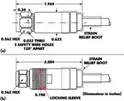
Second, the envelope dimensions and mass had to be quite close to those of the original connectors. The density of connectors in military aircraft with their close spacing mandated a hard size restriction. In no case could the ETNC connector outer diameter, originally 0.63 inches, exceed 0.7 inches. Despite the increased mechanical complexity of the new design, this requirement has also been satisfied. Figure 2 compares the outlines for tie wire and self-locking versions of the ETNC plug nonreplaceable connectors for 0.35" cable.
Third, the original resistance to harsh environments had to be maintained. The assemblies had to provide reliable performance over the -55° to +200°C temperature range and from below sea level to 70,000 feet of altitude even when subjected to vibration levels up to 25 gs. An internal engineering test and evaluation program has shown that these designs still meet the stringent MIL-T-81490 and MIL-C-87104 requirements with the self-lock mechanism, all with a minimal increase in size and mass. Finally, there had to be a positive lock for the locking mechanism such that it is clear both visually and tactilely when the mechanism is engaged.

The construction and operation of the self-locking connector is illustrated in Figure 3 . The self-locking design is intended to eliminate the need for lock wiring the coupling nut in place with tie wire. The connector will still need to be tightened to the mating connector via the use of a torque wrench. The locking feature is achieved via the locking sleeve. When in the disengaged position the coupling nut turns freely allowing the mating of the connector to its female counterpart. No modifications are required to the female connectors. To lock the connector the locking sleeve is rotated until the tabs fall inside the groove "B"; the locking sleeve is then slid forward. To disengage the locking mechanism, the locking sleeve is pulled back and rotated a quarter turn until the tabs on the locking sleeve are inside slots "A." To assist in hand operation, the outside of the locking sleeve has a knurled finish.
In addition to the ETNC and SMA connectors illustrated, self-locking SC and N connectors are also available. As shown by the ETNC connector, the self-lock feature can be applied to 90° right angle connectors as well as 45° angled connectors. It can also be applied to replaceable head connectors. In fact, any assembly equipped with M/A-COM replaceable head connectors can be converted from tie wire connectors to self-locking connectors simply by exchanging the field replaceable heads; there is no change in performance. All electrical, mechanical and environmental specifications are preserved.
The self-lock connectors can be provided on any compatible cable size. SMA interfaces can be provided on cables from 0.09" to 0.35" OD. ETNC is suitable for cables from 0.15" to 0.50" OD. The M/A-COM cable assembly catalog contains a complete connector-cable compatibility matrix.
M/A-COM Inc., Lowell, MA (800) 366-2266; Europe +44 1908-574-200. Circle No. 308

