A planar dual-band circular antenna system for a chemical wireless sensor network uses four antennas, with one antenna selected at a given time using a SP4T switch. This work describes one of the antennas used to transmit sensor information to a nearby hub operating in the industrial, scientific and medical (ISM) bands. The antenna comprises concentric shorted annular rings of substrate integrated waveguide (SIW) and includes a circular patch at its center. It radiates two patterns, one omnidirectional in the azimuth plane at 2.4 GHz and one unidirectional in the elevation plane at 5.8 GHz.

Planar dual-band RF antennas have the reliability and simplicity for integration with chemical sensors that operate at infrared wavelengths1 with associated optoelectronics. The ISM band antennas are employed for high quality data transmission. The SIW structure has been used widely in high performance planar RF circuits.2 It exhibits a high production yield, integrates easily with other components and supports high data rate transmission.3, 4 Several types of passive and active RF circuits have been proposed and demonstrated using SIW technology, including resonators, couplers, antennas and amplifiers.5, 6
A loop antenna with dual-band omnidirectional patterns is described by Liu et al.7 A compact design with two modes at a single resonant frequency with two input probe feeds for MIMO applications is done in a complex multilayer structure but has low gain.8 Liu et al.9 describe a circular patch antenna with a bandwidth of less than 0.5 GHz for Wi-Fi applications. Its structure is based on adding a set of conductive vias. It has a gain of 6 dB but is just single band. In this work, a directional dual-band SIW antenna operating in the ISM bands is demonstrated for use in a wireless sensor network for remote monitoring of chemical contamination.
ANTENNA DESIGN
A single layer, dual-band circular antenna fed with two probes uses SIW cavities. It comprises a circular patch at the center operating at 5.8 GHz surrounded by an annular slot ring operating at 2.4 GHz. The antenna design shown in Figure 1 is based on previous work described by Liu and Guo.10 Its dimensions are listed in Table 1. In this work, a SIW outer ring is added with via holes that enable a good impedance match and isolate port 1 from frequencies above 2.4 GHz.10-13 The outer antenna has two radii, R1 and R2, with a slot width w1. The inner antenna has a radius R3 and resonates at 5.8 GHz. A Taconic RF-30 substrate is used with a thickness, t, of 1.52 mm and a dielectric constant of 2.78. The resonant frequencies of different modes for the outer antenna are calculated using Equation (1):14
 (1)
(1)
where indexes mn define the mode order, er is the dielectric constant and c is the velocity of light in a vacuum. Kmn is the eigenvalue obtained according to the boundary conditions. The resonant wavelength of the TM10 mode is approximately equal to the average circumference of the resonant ring, where Rave = (R1+R2)/2.

Figure 1 Antenna geometry: top view (a) and side view (b).
In addition to the simple cavity model, the structure can also be considered a SIW cavity bounded by electric walls between the inner and outer radii.11 According to theory, the electrical field has a z direction component, with an arbitrary position point (r, f, z) in the SIW annular cavity, as shown in Figure 1. The electric field in cylindrical coordinates can be estimated using Equation 2:10
 (2)
(2)
SIMULATION
The antenna is simulated using HFSS and CST software; CST is based on the integral method, and HFSS is based on the finite-element method. The two antennas in Figure 1 are well isolated with the SIW metalized vias. The TM10 mode current distribution at 2.4 GHz is concentrated around the outer antenna (see Figure 2a) and produces a quasi-omnidirectional pattern. The TM11 mode current distribution of the inner patch antenna (see Figure 2b) produces a unidirectional broadside radiation pattern.

Figure 2 Current density of the TM10 mode at 2.4 GHz (a) and the TM11 mode at 5.8 GHz.
MEASUREMENT
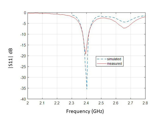
A photograph of the antenna is shown in Figure 3. The aimulated versus measured reflection coefficients shown in Figure 4 are in good agreement except for a slight frequency shift of the TM11 mode, which may be caused by position displacement of the probe feed after fabrication.
The measured relative bandwidth is around 89 MHz at 2.4 GHz and 220 MHz at 5.8 GHz, corresponding to 2.2 percent and 5.7 percent bandwidths, respectively.

Figure 3 Photograph of the prototype antenna: top (a) and bottom (b).

Figure 4a Simulated vs. measured antenna reflection coefficient: |S11| for 2.4 GHz operation.

Figure 4b Simulated vs. measured antenna reflection coefficient: |S22| for 5.8 GHz operation.

