
CASIMIR FORCE STUDY
In Part I (May Issue), it is shown that a combination of a primary shunt switch, DGS structures and secondary shunt switches behave like a metamaterial. In Part II (June Issue), improvement of resistance to stiction of the MEMS switch using metamaterial layers within the design of resistive switch contact is covered. Here in Part III, the metamaterial layers are used as part of the signal line contacts to realize capacitive switch to improve stiction and hence reliability.
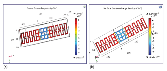
Figure 11 Surface charge density of a shunt switch with serpentine signal line and (a) with and (b) without metamaterial.
To get more insight into the repulsive Casimir forces generated in these structures, a detailed study of a shunt switch with serpentine signal line with and without metamaterial underneath was carried out using COMSOL software. Figures 10 to 12 show electric field distribution, surface charge distribution and electric surface stress tensor of a shunt switch with serpentine signal line with and without metamaterial underneath.
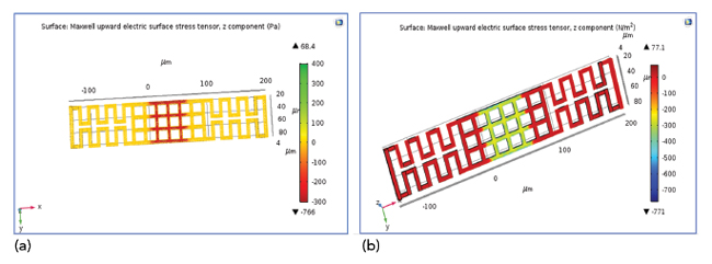
Figure 12 Electric surface stress tensor of a shunt switch with serpentine signal line and (a) with and (b) without metamaterial.
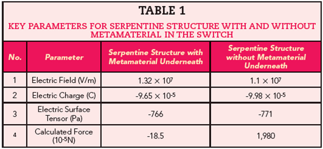
From these results, one can estimate Casimir force. The estimated Casimir force of a shunt switch with serpentine signal line with and without metamaterial underneath is shown in Figure 13 and Table 1 shows key parameters for the serpentine structure with and without the metamaterial. As observed, the structure with metamaterial underneath exhibits Casimir repulsive force.
To verify the accuracy of the simulations, sample structures were fabricated using the PolyMUMPs process and characterized. As an example, the metamaterial inspired MEMS shunt switch shown in Figure 15 (Part I, May Issue) was fabricated and characterized. The SEM and optical microscope images of the fabricated structure are shown in Figure 14. Both primary and secondary switches were experimentally characterized and Eigen frequency, CV characteristics, profiling and LDV plotted. It was observed that the results obtained from the simulations matched with measured data.
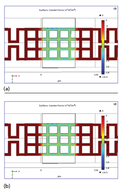
Figure 13 Estimated Casimir Force of a shunt switch with serpentine signal line and (a) with and (b) without metamaterial.
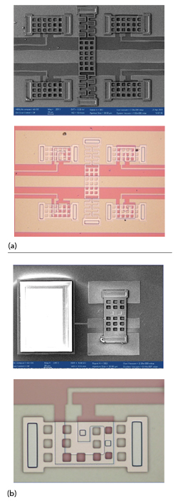
Figure 14 SEM image and Optical Microscope images of (a) primary and (b) secondary shunt switches.
Figure 15 and 16 show the measured results (all the measurements were done on bare die). It was observed that by using serpentine beam, pull in voltage reduced by 9 V. Work on different packages suitable for the present application was also done separately.11-12 Using these techniques, measurements were carried out after packaging without noticing significant changes in the switch performance.
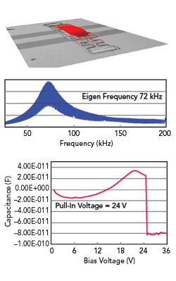
Figure 15 Plots of measured Eigen frequency and pull-in-voltage of the primary shunt switches.
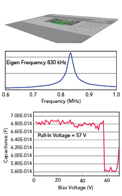
Figure 16 Plots of measured Eigen frequency and pull-in-voltage of the secondary shunt switches.
SUMMARY
RF-MEMS switches can provide new solutions for the 5G and IoT applications in which reconfigurable broadband and frequency-agile devices, like high-order switching components, tunable filters, multi-state attenuators and phase shifters will be necessary to enable mmWave communications, small cells and advanced beamforming. 13-14
As discussed in Part I and Part II of this series, reliability, packaging and integration with standard technologies, were the primary aspects that restricted the usage of MEMS devices in commercial markets.15-18 Part III highlighted the research efforts that targeted the reliability concerns by exploiting Casimir effect in metamaterial inspired MEMS switch, resulting noteworthy improvement in switch characteristics for 5G and IoT applications.19
In this three-part article, the metamaterial structures described are split rings. However, other metamaterial structures can be used, provided those structures provide similar permittivity and permeability characteristics within the desired range of frequencies. For instance, a topology inspired Möbius transformation MTM (metamaterial) structures (meaning a structure that forms a continuous closed path that maps onto itself) can be considered advantageous for generating repulsive Casimir forces.9 Although this series of articles described specific new configurations of MEMS switches, these are just some embodiments of designs that are merely illustrative of the principles and applications of the present invention.1 It is therefore to be understood that numerous modifications can be made to these designs that utilize the same principals demonstrated here.
References
- Shiban Koul, Ajay Poddar, Ulrich Rohde, “Microelectromechanical Switch with Metamaterial Contacts,” US Patent Pub. No. 02161415A1.
- Astrid Lambrecht, “The Casimir Effect: a Force from Nothing,” Physics World September 2002.
- F. Intravaia and C. Henkel, New Frontiers of Casimir Force, Santa Fe, New Mexico, 2009.
- U. Leonhardt and T. G. Philbin, “Quantum Levitation by Left-Handed Metamaterials,” New J. of Physics, August 2007.
- Mercado et. al, “A Mechanical Approach to Overcome RF MEMS Switch Stiction Problem,” ECTC 2003.
- Chaitanya Mahajan, “Design and Analysis of RF MEMS Switches (70 Ghz to 130 GHz), M. Tech dissertation, CARE, IIT Delhi, May 2018.
- J. Sun, X. K. Hua and L. Gao, “Repulsive and Attractive Casimir Forces between Magnetodielectric Slabs,” Solid State Commun., Vol. 152, No. 17, September 2012, pp. 1666–1669.
- V. Yannopapas and N. V. Vitanov, “First-Principles Study of Casimir Repulsion in Metamaterials,” Phys. Rev. Lett., Vol. 103, No. 12, September 2009, pp. 120401.
- Ulrich Rohde, Ajay Poddar and Shiban Koul, “MTM: Casimir Effect and Gravity Wave Detection” APMC 2016.
- Xudong Chen et. al,” Robust Method to Retrieve the Constitutive Effective Parameters of Metamaterials,” Phy. Rev. E70, 016608, July 2004.
- S. Chaturvedi, S. Bhalke, M. Bhat K., G. Sai Saravanan, R. Muralidharan and Shiban K. Koul, “EM Simulation and Development of Wafer Level Micro-Packaging Technique for GaAs-based RFMEMS Switches,” Compound Semiconductor Manufacturing Techniques (CSMANTECH) Conference, May 17-20, 2010, Portland, Ore., U.S., pp. 303-305.
- S. Chaturvedi, “Modelling of Packages for MMICs and MEMS, Ph.D. Thesis, IIT Delhi under the supervision of Shiban K Koul,” CARE, IIT Delhi, 2012.
- L.-Y. Ma et al, “Comprehensive Study on RF-MEMS Switches Used for 5G Scenario,” IEEE Access, Vol. 7, pp. 107506–22, 2019.
- J. Iannacci et. al, “RF-MEMS Monolithic K and Ka Band Multi-State Phase Shifters as Building Blocks for 5G and Internet of Things (IoT) Applications,” MDPI Journal, Sensors, 2020.
- S. Dey, S. K. Koul, A. K. Poddar and U.L. Rohde, “RF MEMS Switches, Switching Networks and Phase Shifters for Microwave to Millimeter Wave Applications,” ISSS Journal of Micro and Smart Systems, April 2020.
- G.S. Karthikeya, S. K. Koul, A. K. Poddar and U.L. Rohde, “Ultra-compact Orthogonal Pattern Diversity Antenna Module for 5G Smartphones,” Microwave and Optical Technology Letters, March 2020.
- S. Dey, S. K. Koul, A. K. Poddar and U.L. Rohde, “Compact, Broadband, and Reliable Lateral MEMS Switching Networks for 5G Communications,” PIERS, pp. 163–171, January 2019.
- S. Dey, S. K. Koul, A. K. Poddar, U.L. Rohde, “Reliable and Compact 3- and 4-Bit Phase Shifters Using MEMS SP4T and SP8T Switches,” Journal of Micromechanical Systems, pp. (99):1-12, January 2018.
- A. K. Poddar, “Slow Wave Resonator Based Tunable Multi-Band Multi-Mode Injection-Locked Oscillator,” Dr.-Ing.-Habil Thesis, BTU Cottbus, Germany, 2014.