SAGE Millimeter will become Eravant in March 2020.
Microwave and mmWave packaging can turn from mostly routine to highly challenging when waveguide ports are required. Integrated waveguide ports typically require a costly process that is difficult to model and build. An extensive collection of package designs may be needed to accommodate different waveguide bands and numerous port configurations. A common alternative is to employ external coax-to-waveguide transitions. Unfortunately, these can be mechanically cumbersome, and they may have high insertion loss or marginal signal integrity.

Figure 1 The Uni-Guide uses the same common RF interface for coaxial connectors, a glass bead hermetically soldered in the housing wall.
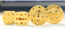
The patent pending Uni-Guide™ waveguide connectors from SAGE Millimeter lowers many of these design and manufacturing hurdles. They provide compact, reliable and cost-effective waveguide flanges that are simply added to standard coaxial ports. Easily swapped with coaxial connectors, they enable greater flexibility for component manufacturers and end-users.
HERMETICAL WAVEGUIDE SOLUTION
A common type of signal port used in hermetic packages uses a glass bead positioned mid-way between a pair of threaded mounting holes (see Figure 1). The threaded holes support a coaxial connector that is easily attached or replaced. This common configuration is used by several connector families, including SMA, 2.92 mm (K), 2.4 mm, 1.85 mm (V), 1.35 mm (E) and 1 mm.
The Uni-Guide waveguide connector joins this group. If the package is designed and manufactured to be hermetically sealed for coaxial connectors, it will retain its hermeticity when using a Uni-Guide waveguide connector. This eliminates the need for an expensive hermetic waveguide process.

Figure 2 Typical insertion loss and |S11| of the Ka-Band Uni-Guide connector.
A trio of Uni-Guide connectors is available for coaxial ports with a 12 mil center pin and two mounting holes spaced 0.48 in. apart, the same arrangement widely used with the 2.92 mm (K) and 2.4 mm connectors. The model SUF-2812-480-S1 is a WR-28 connector covering 26.5 to 40 GHz with 0.5 dB typical insertion loss. The SUF-2212-480-S1 WR-22 connector covers 33 to 50 GHz and has 0.6 dB insertion loss, and the SUF-2812-480-S1 WR-19 connector, covering 40 to 60 GHz, has 0.7 dB insertion loss. All three have 20 dB typical return loss and handle 100 W RF power. The measured insertion loss and |S11| of the Ka-Band Uni-Guide is shown in Figure 2.
Additional Uni-Guide models designed for glass beads with pin diameters of 9, 15, 20 and 50 mils and various mounting configurations are being developed to cover all standard waveguide bands from 8.2 to 110 GHz.
PORT TYPE AND ORIENTATION CHANGES

Figure 3 Pairs of Uni-Guide connectors can be combined to create band-to-band adapters or 90 degree twists.
While they provide an easy way to implement waveguide ports, Uni-Guide connectors have additional benefits. Rotating them yields a 90 degree change in port orientation to form various integration options, and a polarity inversion is achieved when a connector is rotated 180 degrees. Pairs of Uni-Guide connectors can be cascaded to create common waveguide components, such as band-to-band waveguide adapters or 90 degree twists (see Figure 3). A center pin bridges the signal path between back-to-back connectors, yielding a compact component that rivals the performance of larger and more costly alternatives.
In many situations, Uni-Guide connectors allow component manufacturers to offer various port configurations so that either coaxial or waveguide test equipment can be implemented. This can reduce the number of costly test systems required for a flexible production environment.
TIME AND MONEY
A custom package design requires electromagnetic simulation, mechanical modeling, design, machining and validation, which can easily take 12 to 16 weeks. A second iteration, if required, extends the development time to 20 to 26 weeks. Using the Uni-Guide waveguide connector with a standard coaxial housing can provide any waveguide port needed - instantaneously, without design or prototyping.
To handle a portfolio of waveguide sizes and port interfaces, a manufacturer could have tens to hundreds of package sizes and styles, building costly inventory that becomes large and wasteful. Now, only a few standard housings and Uni-Guide connectors will support many coaxial, waveguide or mixed interface products. The flexibility of the Uni-Guide waveguide connector eliminates many adapters, transitions and waveguide twists.
SAGE Millimeter
Torrance, Calif.
www.sagemillimeter.com
