Sidebar: Highly Integrated Silicon RFICs Enabling 57 to 71 GHz Phased Arrays
To use the abundant mmWave spectrum being allocated by regulators, operators must field compact and affordable base stations. Phased array architectures offer the best performance and flexibility for many use cases, yet the number of elements in the array, with transceivers at each element, demands seemingly conflicting transceiver requirements for high integration and low cost. Fortunately, the extension of silicon’s economies of scale to mmWave frequencies over the last decade has created the technology platform enabling the development of these RFICs by companies such as Sivers IMA.

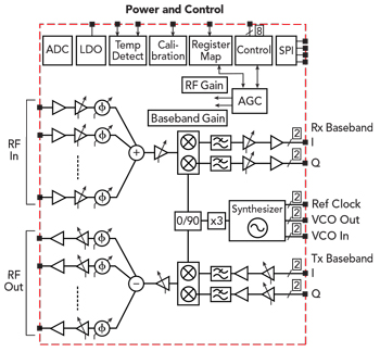
Sidebar Figure 1 TRX BF01 transceiver block diagram.

Sidebar Figure 2 The BFM06010 module integrates the transceiver RFIC and antenna array into 16 Rx and 16 Tx beamforming channels.
Sivers IMA’s TRX BF01 is a highly integrated phased array RF transceiver developed for dynamic wireless communications infrastructure, such as mesh networks. It operates across 57 to 71 GHz and meets the IEEE 802.11ad specification, supporting channels 1 through 6, with center frequencies from 58.32 to 69.12 GHz. The transceiver integrates 16 Tx and 16 Rx signal paths and can be tiled into larger arrays (see SB Figure 1). The transceiver uses a direct conversion architecture for both Tx and Rx, connecting from the baseband modem to 60 GHz patch antennas via a low loss stripline connection.
The transmit path includes integrated linear power amplifiers, providing a combined output power of greater than 22 dBm. The receive path includes low noise amplifiers with 7 dB noise figure, providing excellent receiver sensitivity, and analog channel filtering to suppress out-of-band interference, making the transceiver robust in a noisy RF environment and tolerant of out-of-band interferers. The transceiver includes a fully autonomous AGC, optimizing the receive gain based on the wanted and out-of-band signal levels, and provides autonomous DC offset and support for LO leakage and I/Q calibration. The error vector magnitude of −27 dB in both the transmit and receive modes supports modulation up to 64-QAM. High resolution phase shifters and signal path amplitude control enable accurate beamforming and reduced side lobes. The transceiver also contains a low noise VCO and fixed-N synthesizer and includes an auxiliary analog-to-digital converter to support various external functions, such as power and temperature measurements. With this level of integration, a complete transceiver system requires very few external components.
To address a range of use cases, the transceiver may be paired with various antenna array configurations. One common use is a distribution link for wireless mesh networks, which requires a link distance of several hundred meters combined with wide azimuth steering to address the different nodes in the mesh. In this scenario, the typical antenna design provides a horizontal steering range of 90 degrees with a fixed vertical beam. The corresponding half power beamwidth is 90 degrees horizontally, 20 degrees vertically. The antenna array can be implemented using a low loss laminate material, such as Megtron 6 or Rogers 3003, and standard printed circuit board fabrication. These materials are robust and proven and are cost-effective for high volume mmWave applications, such as wireless communications and automotive radar. Each antenna element has a gain of 10 dBi with flat frequency response from channels 1 through 6. The combination of the patch elements in a typical antenna array configuration with a single RF transceiver produces 16 Tx and 16 Rx antenna elements, providing 22 dB minimum gain on boresight (see SB Figure 2).

Combining the RF antenna module with a suitable baseband device, such as IDT’s Rapidwave™ RWM6050, provides a complete 60 GHz communications subsystem, which is integrated with a network processor to create a wireless mesh network node. SB Table 1 provides a system gain analysis, illustrating how the twin goals of wide steering range and long distance can be accomplished for a wireless mesh distribution network.
