

Figure 1 Final CPW-fed planar monopole antenna configuration (a) and prototype (b).
A compact dual-band linearly and circularly polarized monopole antenna employs an inverted L-shape and an asymmetric ground plane fed by a coplanar waveguide (CPW). The inverted L-shape strip produces an orthogonal component in the ground plane and monopole distinct from its original linear polarization (LP). By embedding a slit on the ground plane, this antenna achieves a broad impedance bandwidth and circular polarization (CP). Measurements demonstrate a 10 dB bandwidth of 92.7 percent from 3.3 to 9 GHz and a 3 dB axial ratio (AR) bandwidth of 57.1 percent from 5 to 9 GHz, capable of covering the 5.725 to 5.85 GHz WLAN band. Meanwhile, LP is also obtained covering the 3.3 to 3.7 GHz WiMAX band. Compared with other recent work, wider axial ratio and impedance bandwidth, as well as a simpler, more compact structure are the key features.
CP radiation has been widely used in the fields of communication, radar and electronic countermeasures.1-3 To achieve CP, several printed monopoles have been proposed.4-10 Augustin and Denidni LP designed a multi-band coplanar monopole antenna with a trapezoidal structure.4 Wang and Hisao5 used an asymmetrical ground plane to excite CP at 1.57 GHz with a simple CPW ground plane width adjustment. Ghobadi and Dehmollaian6 introduced CP operation with two arms of different lengths in a simple printed monopole. Others used slots in the ground plane,7 four notch slots,8 feed positioning with U- and E-shaped slots,9 slotted monopoles,10 S-shaped slots,11 inverted L-slits on the ground and feed networks composed of three Wilkinson power dividers.12 These are examples of the various techniques proposed for fabricating CP monopole antennas.
Due to the narrow CP bandwidths of these approaches, several wideband CP monopole antennas were introduced.13-16 Kumar and Harish13 described a slot monopole antenna with a power division network. It achieved a 30 percent AR bandwidth by adjusting the size of the slot; yet it was large in size with a complex geometry. By parallel-aligning an inverted L-shaped strip and cutting an inverted L-shaped slot on the ground plane,14 a CP bandwidth larger than 30 percent was achieved. Broadband CP radiation could be also produced by moon-shaped15 or chifre-shaped16 monopole antennas. However, most of the broadband CP monopole antennas with slots and stubs or embedded complex structures13-18 are large in size.
In this article, a novel compact dual-band LP and CP monopole antenna with an inverted L-shaped monopole and an asymmetric ground plane for WiMAX and WLAN applications is described.

Figure 2 Monopole antenna prototype designs.

ANTENNA CONFIGURATION
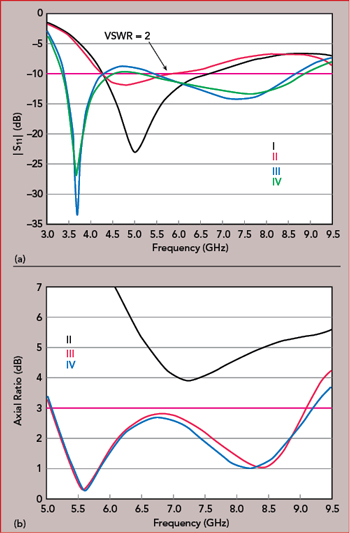
Figure 3 Simulated |S11| (a) and AR (b) of the prototype antennas.

Figure 4 Simulated electric field distributions: antenna II at 5 GHz (a) and antenna III at 5.6 GHz (b).

Figure 5 Surface current distribution after HFSS optimization, at 0 degrees (a) and 90 degrees (b).
The final CPW-fed monopole antenna geometry is shown in Figure 1. The antenna is printed on an FR4 substrate with a dielectric constant of 4.4 and loss tangent of 0.02. An asymmetric ground plane with a slit etched on the left is introduced to excite broadband CP and obtain a good impedance match. To obtain a wider impedance bandwidth, an impedance matching structure is employed at the base of the asymmetric ground and the monopole radiator. Broadband CP is obtained with two adjacent CP modes combined by adjusting the size of the inverted L-strip and length of the slit etched on the ground plane. To maximize the 3 dB AR bandwidth while maintaining the return loss better than 10 dB, the dimensions of the inverted L-strip, the slit length and CPW feed line were optimized in HFSS (see Table 1).
Shown in Figure 2 are four prototypes built during the process of validating the design. S11 and AR are compared in Figures 3a and 3b, respectively. Due to weak radiation in the vertical direction, CP is difficult to generate in a traditional monopole. This is illustrated by the electric field vectors in Figure 4a. The vertical electric field vectors of the two ground planes are in opposite directions, resulting in small vertical components. Therefore, linear horizontal polarization with a large value of AR is shown in Figure 3b (antenna II).
In general, CP is generated by two orthogonal E vectors with equal amplitudes and a 90 degree phase difference. It is defined as

where E is the instantaneous electric field vector, EHor and EVer denote the respective electric field vectors in the horizontal and vertical planes and δ is the phase difference. If the amplitudes of EHor and EVer are equal and δ = ±90 degrees, the polarized wave is right-hand circular polarization (RHCP) or left-hand circular polarization (LHCP).18 The AR can be used to represent the characteristics of the polarization. The AR is defined as RHCP or LHCP19-20 and is expressed as

LP, CP and elliptical polarization (EP) are three types of polarization. For perfect LP, the AR is infinite; for perfect CP, the AR is 0 dB; EP is considered to lie between LP and CP. Because a perfect CP wave with AR = 0 dB is ideal, CP is typically defined as an AR value of less than 3 dB.
The asymmetric ground plane with an inverted L-strip feed generates EHor and EVer, but it excites EP. So, an asymmetric ground plane with a horizontal slit on the left ground plane is employed to generate two orthogonal modes with a 90 degree phase difference. Using this method, the amplitudes of EHor and EVer are almost equal and exhibit a 90 degree phase difference, exciting CP (see antennas III and IV in Figures 3b and 4b). As shown in Figure 4b, a vertically polarized component is produced by an asymmetric ground plane that produces vertical magnetic field vectors in the right ground plane. To achieve a wider impedance matching bandwidth, a matching structure is introduced, which results in the improvement seen in Figure 3a (antenna IV).
PARAMETRIC STUDY
CP depends mainly on the dimensions of the inverted L-strip, height of the ground plane and length of the slit. Figure 5 shows the surface current distribution for each of the orthogonal polarizations after HFSS optimization, with the optimized dimensions listed in Table 1.
Figure 6 shows the effects of L1 and d on antenna impedance match and AR, as simulated in MATLAB at 7 GHz. Simulation and analysis show that the best impedance and AR properties occur for L1 = 6.25 mm and d = 3.25 mm. S11 and AR curves for various Lf values are shown in Figure 7. An improved impedance match and a downward shift of the S11 minima is observed as Lf is varied from 21 to 23 mm. Meanwhile, for Lf greater or less than 22 mm, CP is degraded. The best S11 and AR performance occurs at around 22 mm. The S11 and AR curves for various Sy values are displayed in Figure 8. When Sy is increased, the second resonance of the reflection coefficient curve shifts upward in frequency. The first and the second CP mode shift upwards as well, widening the AR bandwidth. To achieve good performance in both the reflection coefficient and the AR, a tradeoff must be made selecting Sy; the best S11 and AR properties occur for an Sy value of approximately 2.75 mm.

Figure 6 |S11| (a) and AR (b) vs. L1 and d.

Figure 7 |S11| (a) and AR (b) vs. Lf.

Figure 8 |S11| (a) and AR (b) vs. Sy.

Figure 9 H-field distribution with rotation at 5.6 GHz.
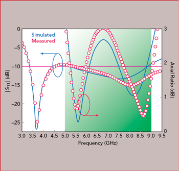
Figure 10 Simulated and measured |S11| and AR vs. frequency.
Figure 9 shows the patch’s simulated magnetic field vectors at 5.6 GHz for four instants of time, as the field rotates from 0 to 270 degrees. As time increases, the magnetic field vectors rotate clockwise, indicating LHCP for z > 0, which is the upper half space. RHCP would be observed for z < 0, or the lower half space.
SIMULATION AND MEASUREMENT
The antenna was simulated using HFSS and fabricated with the optimized dimensions shown in Table 1. Simulated and measured antenna S11 and AR vs. frequency are shown in Figure 10. Measured and simulated impedance bandwidths are 92.7 percent (3.3 to 9 GHz). CP bandwidths are 57.1 percent, from 5 to 9 GHz at a center frequency of 7 GHz. This performance can provide full coverage of the 5.725 to 5.85 GHz WLAN band. LP is obtained, as well, covering the 3.3 to 3.7 GHz WiMAX band. Excellent agreement is observed between simulation and measurement except for mismatches attributed to poor quality SMA connectors and fabrication tolerances.
Numerical and experimental radiation patterns of the antenna at 3.7, 5.6 and 8.3 GHz for the xoz and yoz planes are plotted in Figure 11 and are in close agreement. When operating at the lower frequency, the antenna radiates with a slot-like pattern for vertical polarization; at the upper frequencies, it radiates with patch-like patterns of RHCP/LHCP polarization. LHCP and RHCP patterns depend on the point of observation, whether it is from the +Z direction (upper hemisphere) or −Z direction (lower hemisphere). The gain and efficiency over frequency are plotted in Figure 12.
CONCLUSION
A compact dual-band LP and CP monopole antenna exhibits a broad 3 dB AR bandwidth by combining an inverted L-strip and a horizontal slit, with two adjacent CP modes coupled together. A 10 dB impedance bandwidth of 92.7 percent (3.3 to 9 GHz) and a 3 dB AR bandwidth of 57.1 percent (5 to 9 GHz) was demonstrated and shows good agreement with measured data.
References
- J. Y. Sze, C. I. G. Hsu, Z. W. Chen and C. C. Chang, “Broadband CPW-Fed Circularly Polarized Square Slot Antenna with Lightening-Shaped Feed Line and Inverted-L Grounded Strips,” IEEE Transactions on Antennas and Propagation, Vol. 58, No. 3, March 2010, pp. 973–977.
- Y. W. Liu and P. Hsu, “Broadband Circularly Polarized Square Slot Antenna Fed by Co-planar Waveguide,” Electronics Letters, Vol. 49, No. 16, August 2013, pp. 976–977.
- Y. B. Chen, Y. C. Jiao and F. S. Zhang, “Polarization Reconfigurable CPW-Fed Square Slot Antenna Using PIN Diodes,” Microwave and Optical Technology Letters, Vol. 49, No. 6, June 2007, pp. 1233–1236.
- G. Augustin and T. A. Denidni, “Coplanar Waveguide-Fed Uniplanar Trapezoidal Antenna with Linear and Circular Polarization,” IEEE Transactions on Antennas and Propagation, Vol. 60, No. 5, May 2012, pp. 2522–2526.
- C. J. Wang and K. L. Hisao, “CPW-Fed Monopole Antenna for Multiple System Integration,” IEEE Transactions on Antennas and Propagation, Vol. 62, No. 2, February 2014, pp. 1007–1011.
- A. Ghobadi and M. Dehmollaian, “A Printed Circularly Polarized Y-Shaped Monopole Antenna,” IEEE Antennas and Wireless Propagation Letters, Vol. 11, December 2011, pp. 22–25.
- G. Li, H. Zhai, T. Li, L. Li and C. Liang, “A Compact Antenna with Broad Bandwidth and Quad-Sense Circular Polarization,” IEEE Antennas and Wireless Propagation Letters, Vol. 11, July 2012, pp. 791–794.
- H. Ren, Y. Yu and Z. Shen, “Broadband Circularly-Polarized Antenna Consisting of Four Notch Slot Radiators,” Electronics Letters, Vol. 48, No. 23, November 2012, pp. 1447–1449.
- Y. Chen and C. F Wang, “Characteristic-Mode-Based Improvement of Circularly Polarized U-Slot and E-Shaped Patch Antennas,” IEEE Antennas and Wireless Propagation Letters, Vol. 11, November 2012, pp. 1474–1477.
- S. A. Rezaeieh and A. Abbosh, “Broadband CPW-Fed Slot Antenna with Circular Polarization for On-Body Applications at ISM Band,” Proceedings of the Asia-Pacific Microwave Conference, December 2012, pp. 1184–1186.
- G. Li, H. Zhai, T. Li, L. Li and C. Liang, “CPW-Fed S-Shaped Slot Antenna for Broadband Circular Polarization,” IEEE Antennas and Wireless Propagation Letters, Vol. 12, May 2013, pp. 619–622.
- Y. J. Hu, W. P. Ding, W. M. Ni and W. Q. Cao, “Broadband Circularly Polarized Cavity-Backed Slot Antenna Array with Four Linearly Polarized Disks Located in a Single Circular Slot,” IEEE Antennas and Wireless Propagation Letters, Vol. 11, May 2012, pp. 496-499.
- T. Kumar and A. R. Harish, “Broadband Circularly Polarized Printed Slot-Monopole Antenna,” IEEE Antennas and Wireless Propagation Letters, Vol. 12, November 2013, pp. 1531–1534.
- S. Ahdi Rezaeieh, A. Abbosh and M. A. Antoniades, “Compact CPW-Fed Planar Monopole Antenna with Wide Circular Polarization Bandwidth,” IEEE Transactions on Antennas and Propagation, Vol. 12, September 2013, pp. 1295–1298.
- B. Hu, Nasimuddin and Z. Shen, “Moon-Shaped Printed Monopole Antenna for Wideband Circularly Polarized Radiation,” Proceedings of the IEEE-APS Topical Conference on Antennas and Propagation in Wireless Communications, September 2013, pp. 825–827.
- R. C. Han and S. S. Zhong, “Broadband Circularly-Polarized Chifre-Shaped Monopole Antenna with Asymmetric Feed,” Electronics Letters, Vol. 52, No. 4, February 2016, pp. 256–258.
- S. L. S. Yang, A. A. Kishk and K. F. Lee, “Wideband Circularly Polarized Antenna with L-Shaped Slot,” IEEE Transactions on Antennas and Propagation, Vol. 56, No. 6, June 2008, pp. 1780–1783.
- J. W. Wu, J. Y. Ke, C. F. Jou and C. J. Wang, “Microstrip-Fed Broadband Circularly Polarised Monopole Antenna,” IET Microwaves, Antennas and Propagation, Vol. 4, No. 4, April 2010, pp. 518–525.
- C. Igwe, ”Axial Ratio of Antenna Illuminated by an Imperfectly Circularly Polarized Source,” IEEE Transactions on Antennas and Propagation, Vol. 35, No. 3, March 1987, pp. 339–342.
- B. Y. Toh, R. Cahill and V. F. Fusco, “Understanding and Measuring Circular Polarization,” IEEE Transactions on Education, Vol. 46, No. 3, August 2003, pp. 313–318.

Figure 11 Simulated and measured radiation patterns at 3.7 (a), 5.6 (b) and 8.3 GHz (c).

Figure 12 Simulated and measured antenna gain and efficiency vs. frequency.