While the natural tendency for mating an SMA or 2.4 mm connector to a test lead of a VNA is to snug it twice with the torque wrench, doing that with these connectors will not improve performance and will damage the threads and internal components of the adapter. Always use a calibrated torque wrench when mating the thread-on connectors; 4 in./lb (0.45 Nm) is not much, but it is tighter than finger-tight.
Finding the source of a poor performing cable assembly is always difficult, especially with new technology. Is it the cable or connector or test setup going south—when it was fine just minutes ago? Having a gold standard that has been tested and verified for stable performance over several months is helpful in these instances.
PREPARATION AND RESOURCES
These are called the mmWave frequencies for good reason. Everything is small, tolerances are tight, equipment is sensitive, you blink and the dielectric bead has disappeared. How each company prepares the cable for terminating is specific, and each manufacturer has unique tricks. The important point for an excellent result is adherence to a set of processes that are repeatable and can be audited. Whether you trim the cable using a blade, a saw or a laser, whether you tin and wick the contact, if applicable, or meter the solder, the adherence to these processes and acceptance of the processes by the manufacturing personnel is paramount.

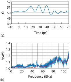
Figure 2 TDR response (a) and VSWR (b) of the final connector design.
Another paradigm shift pertains to manufacturing. Cable manufacturers are used to making L- through V-Band cables, with certain expectations for the time to manufacture and test and yields. The E- and W-Band cables are different; everything is slower by at least an order of magnitude: the time to prep and inspect the cable, terminate the connectors, identify where a problem resides (e.g., cable, connectors, termination, test setup) or when to accept failure and move on. Making this transition is easier if the manufacturing personnel are dedicated to the product rather than switching back and forth between high and low frequency cable assemblies.
SUMMARY
Compare Figure 1, which shows the connector’s performance at the beginning of the development process, to Figure 2, which shows the performance of the finished design, now in production. Connector discontinuities that were in the 7 Ω range, inductive to capacitive, are now in a 2 Ω range, and the VSWR confirms a cable assembly performing well to 110 GHz.
This article is a primer discussing some of the common problems encountered when designing and developing 110 GHz cable assemblies, rather than an in-depth, technical, cause-solution explanation. Users of these cables will find information to help select a supplier and some shortcuts to diagnose problems. The discussion highlights some of the reasons why a 110 GHz cable assembly that looks identical to a Ka-Band cable assembly and whose SMPS connector looks very similar to the SMPM connector, costs 3 to 5× more than the Ka-Band cable assembly.
The 110 GHz cable assembly market is growing and, as more commercial systems become available, demand will rise. After the initial use in automotive radar and wireless backhaul, there is interest in other communications services, including the soon-to-be launching satellite constellations such as OneWeb and Telesat.
