

Version 8 of Mician’s µWave Wizard software combines the flexibility of the 2D/3D finite element method (FEM) with the speed and accuracy of traditional mode matching techniques. The benefit of mode matching lies in its ability to perform and combine sub-circuit type full-wave simulation with full parameterization of structural geometries using µWave Wizard’s built-in optimizers.
The fast and easy composition of complex RF structures using basic building blocks eliminates the need to create a full 3D model of the entire structure and speeds the development process. In addition to its fast and powerful numerical methods, µWave Wizard offers flexibility and openness, including a COM API interface and CAD export formats that interface with most mechanical design tools.
RIBBON GUI
Version 8 offers a ribbon graphical user interface (GUI) that makes a convenient, user-friendly environment, even for a beginner. The attractive icon-based shortcuts and controllers distributed across the ribbon (see Figure 1) help the user to understand each task quickly and easily. The project tree view provides all information about the current project, such as frequency settings, variables by type (real, optimization, tune and equation with complex mathematical expressions), circuits and sub-circuits and default settings like units, accuracy, symmetries and material properties. The new GUI separately identifies the variables that correspond to the circuit currently selected. µWave Wizard’s schematic editor supports zooming, drag and drop, cut and paste and undo/redo functionality for the elements and circuits and contains many useful macros. All of these editing options are easily found under ribbons. Another new feature enables changes at both the project and circuit levels, as desired.
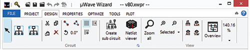
Figure 1 User-friendly ribbon-based GUI.
The OpenGL based 3D viewer provides visualization of circuit geometries, mesh files and field patterns and enables the graphic to be exported to common CAD formats like STL, DXF, VRML and STEP. With Version 8, real-time 3D visualization of all library elements is introduced. When both the element editor and the 3D viewer are open at the same time, a change of a geometric parameter in the element editor will be immediately visible in the viewer.
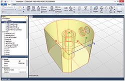
Figure 2 The modeler is a 3D editor for creating and modifying geometric models of 3D and planar structures.
One of the main assets of µWave Wizard is the library module, which has over 450 key building elements, such as steps, irises, cavities, bends, junctions, coaxial probes, entire structures (e.g., tapers, OMTs) and radiation. Searching for an element is possible by using the new filtering option, filtering the component by name – even by a part of the name of the desired element – or by using port properties.
MODELER
Although µWave Wizard’s elements offer high flexibility, some designs may require the creation of user-defined elements. µWave Wizard Version 8 now includes a modeler which is directly accessible through the new µWave Wizard modeler library. The modeler (see Figure 2) is a versatile 3D editor enabling the creation and modification of geometric models of 3D and planar structures. Modeling is based on a constructive solid geometry (CSG) technique, where complex geometries are created from simple objects called primitives (e.g., boxes, cylinders, rectangles) and then modified and/or subjected to Boolean operations (e.g., union, subtraction, intersection). For example, a partial height post in a cavity is created by first creating a box, then a cylinder and subtracting it from the box. Each time an object is created or modified, the action is added to the object’s operation list, which acts as a blueprint. This makes the design and further modification of structures simple and fast.
A different approach to the design comprises building the structure in two steps. First, a two-dimensional cross-sectional profile is created using 2D primitives. Second, the profile is extruded along a line to get a 3D structure. Other features of the construction include arrays of objects using the cloning tool, fillets to create accurate models of devices built by machining and structures with ruled surfaces and surfaces of revolutions.
This new feature not only facilitates easy building of structures, it also provides a simple and powerful way to change structures once built. Thanks to parameterization of all operations on geometries, the dimensions and other parameters of a structure can be quickly changed without building the structure again. The user simply selects the desired operation on the screen and types a new parameter value; the structure is automatically rebuilt according to the new parameters.
The modeler incorporates a flexible variable mechanism that not only enables the introduction of simple numerical values but also complex equations, utilizing a range of built-in predefined functions. Further design flexibility is achieved by utilizing multiple nested coordinate systems. All variables are synchronized between the modeler and µWave Wizard’s GUI. The connection between modeler elements (even complex structures) is supported by the multimodal scattering matrix. No normalization or manual sorting of modes is necessary. The user simply connects the corresponding waveguide ports between the elements.
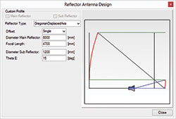
Figure 3 Synthesizing a Gregorian DAX antenna with the reflector synthesis tool.
Version 8 includes several additional features and enhancements:
Direct and Iterative Solver: µWave Wizard uses 3D FEM as an additional method to solve Maxwell’s equations, offering high flexibility in modeling capabilities (i.e., geometry, material fillings, field and loss calculations). Now with µWave Wizard Version 8, two new 3D FEM solvers – one direct and one iterative – have been introduced. They use a set of hierarchical basis functions, up to third order, and curvilinear tetrahedral elements to solve the wave equation. The use of higher order basis functions leads to more accurate approximations of the electromagnetic fields, where curvilinear tetrahedral elements result in accurate shape modeling of curved and complex geometries. The field calculation and mode matching interface have been extended for full compatibility with existing modules. The iterative solver uses a multilevel preconditioner for greater efficiency.
Reflector Synthesis Tool:The reflector computation, which was extended by a reflector synthesis tool since the previous version (7.11) of µWave Wizard, has been further modified in Version 8. This tool is now capable of designing several reflector and sub-reflector types, ranging from very basic structures like parabolic and hyperbolic to more complex structures such as displaced axis (DAX) Cassegrain or Gregorian reflectors (see Figure 3). This tool also offers the user the facility to create any user-defined reflector or sub-reflector.
Parallelization: µWave Wizard offers different levels of parallelism for efficient use of multi-core CPU architectures. The parallelization of all 3D FEM solvers and many of the mode matching and 2D FEM modules significantly speeds up the simulation of a single project.
Mician
Bremen, Germany
www.mician.com