A Novel Tapered Slot PCS Antenna Array and Model
An antenna array comprising multiple tapered slot radiators and its microstrip feed network has the capability to be etched on a single piece of thin dielectric circuit board, resulting in the relatively inexpensive mass production of a highly consistent product. A modification to the conventional tapered slot aperture that results in improved SWR performance is presented. An accurate radiation pattern prediction of arrays of tapered slot antennas is also presented. Measured results of actual hardware indicate good correlation with the predicted model in both the main beam and back lobe regions.
Ronald A. Marino
Celwave Division of Radio Frequency Systems Inc.
Marlboro, NJ
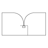
The tapered slot antenna (TSA) is a wideband element that performs extremely well in PCB applications. This element has also been referred to as a notch or Vivaldi antenna. The antenna consists of a microstrip-to-slotline transition (often  referred to as the balun section). Figure 1 shows how the slotline tapers gradually, forming the radiating section. This design requires a single board that is
  etched on both sides. The high quantity of metallization remaining on the slot side of the board acts as the ground plane for the microstrip feed. This preferred configuration produces the real estate for a power divider network when arraying multiple tapered slot elements on the same board, as shown in Figure 2 .
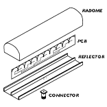
 An antenna array of this design requires few piece parts. The major components of the antenna are the PCB, reflector, connector and radome, as shown in Figure 3 . Fabrication requires the application of an adhesive transfer tape, adherence of the PCB, screwing on a connector, soldering one joint and fastening the radome. The use of an extruded reflector and radome with the printed circuit technology results in the relatively inexpensive mass production of a highly consistent product.
In addition to the array's low fabrication cost, a means to predict its radiation pattern performance efficiently has been achieved. A method to accurately model TSAs and arrays consisting of TSAs has been accomplished with the use of the Electromagnetic Surface Patch Code Version 4.0 (ESP4) computer program. ESP4 employs the method of moments for the analysis of radiation patterns and scattering from three-dimensional geometries consisting of an interconnection of thin wires and perfectly conducting or thin dielectric polygonal plates. The computer code is based on the electric field integral equation and, therefore, is applicable to modeling both open and closed surfaces. The program utilizes surface patch modeling (as opposed to wire grid modeling). It is claimed that surface patch modeling produces a more accurate representation of currents on the surface and requires fewer unknowns per square wavelength than a wire grid model.1 An examination of other electromagnetic codes 2,3 and ESP4 has produced the conclusion that ESP4 is the most efficient for many applications, especially radiation pattern determination.
Single-element and Array Performance
Single TSA elements and TSA arrays were fabricated on commercial-grade microwave laminate materials to evaluate their performance. The commercial-grade materials had dielectric constants in the 3.00 to 3.38 range. Thickness ranged from 0.030" to 0.032", providing the minimum mechanical requirement to prevent warpage. The thickness of the laminate is a cost driver. It is typical for the material cost to double when the thickness doubles and, therefore, it is important to choose a material that is as thin as possible while achieving performance requirements.
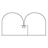
The SWR performance of the conventional printed circuit TSA is better than 2 over a 2-to-1 bandwidth. Improving the match of the balun section4 produces similar SWR performance over three bandwidths. SWRs of less than 2 have been achieved over five bandwidths, as shown in Figure 4 , for the fixed-radius TSA (patent pending) shown in Figure 5 . Note that the SWR performance is achieved with a conventional balun. The data also
  show that an SWR of less than 1.5 is achievable over bandwidths in excess of 55 percent. The fixed-radius taper extends beyond that of the conventional design, forming a continuous transition without abrupt corners. The width of the taper's extreme edges is approximately l/3 at its lowest operating frequency. The TSA's E- and H-plane pattern beam widths are narrower than that of a l/2 dipole with a directivity approximately 2 dB higher.
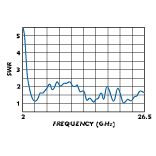
A machined version of the fixed-radius TSA that does not incorporate printed  circuit technology has also been investigated. The feed for this version was a coax in which the outer metal jacket was removed and fed through the center of a TSA plate (0.125" thick). The center conductor of the coax transverses the slot and is shorted to the other TSA plate. The SWR performance is shown in Figure 6 . An SWR of 2.5 is achieved from 2.5 to 26.5 GHz (more than a 10-to-1 bandwidth). This method of design offers the capability of achieving higher power levels relative to those of printed circuit technology.
It is apparent from the measurements that the fixed-radius TSA has extremely broadband SWR performance. It has further been discovered (from modeling using finite-difference time domain methods) that the weak link in the SWR performance can be found in the transition to slotline. The TSA's ideal impedance, as verified by both modeling and measurement, was determined to vary only between 70 and 80 W over frequency when the aperture is wider than l/2.
The use of an array of TSAs over multiple bandwidths is attractive, however, other parameters - such as pattern performance and gain - degrade. This degradation is primarily the effect of the element spacing and element pattern shape. Depending upon the element pattern shape, element spacings in excess of l are possible without performance degradation. Performance degradation usually takes the form of high sidelobes and/or grating lobes. When the sidelobes or grating lobes reach high levels, the power available to the main lobe is reduced, resulting in lower gain. A dual-band element covering the cellular (824 to 960 MHz) and PCS (1850 to 1990 MHz) bands has been developed and fabricated. An SWR performance of less than 1.2 was achieved over both bands. Initial array performance has indicated that good radiation performance without the presence of significant grating lobes is achievable over both bands.
Even though the overall performance may not be achievable over a 5-to-1 bandwidth, the design offers robust qualities for narrower bandwidths using commercial-grade laminates and processes. Commercial-grade PC laminate products suffer because their electrical and mechanical properties are relatively less precise. This wider variation requires the PC antenna design to be over designed to compensate for the material tolerances. The fixed-radius TSA array with its broadband SWR performance and relatively inexpensive fabrication costs is therefore ideal for commercial applications.
Model Details
The TSA was determined to be an ideal candidate for the ESP4 computer program. The majority of the model is composed of four plates: two polygonal plates for the TSA and two rectangular plates for the attached reflector. Figure 7 shows the geometry of the TSA and reflector plates. The program requires that all plate-to-plate junctions have a common side (which is why the reflector is divided into two plates). The feed used for exciting the TSA consists of four segments whose endpoints are attached to the TSA's plates.
Other advantages of this model are its simplicity and short development and run times. To determine the radius coordinates of the TSA using a simple computer program (listed in Appendix A), the entire model typically requires less than 10 minutes to develop and less than five minutes to run (200 MHz Pentium Pro/Windows" NT). To develop an array of TSAs, the single TSA coordinates are simply stepped and repeated and the reflector size is enlarged. The run time for a 10-element TSA array (1500 modes) is 30 minutes. If a different pattern cut or new voltage excitation is required, the program need not recompute parameters (specifically the impedance matrix) and the run time is reduced from 30 to eight minutes. The computer memory required to run a 2000-mode geometry is approximately 50 Mb (doubling the number of modes quadruples the required memory).
Though the model generation for the TSA array is quite simple, a few details other than those required by the code must be applied. Numerous inputs are required that describe the plate details. Of these inputs, two are the maximum segment size of the surface patch and the generating side. ESP4 features an algorithm that divides the plates into surface patch modes. The segment size determines the number of modes generated on the plate. The algorithm begins to produce a grid by drawing a set of lines, which start adjacent to the generating side and continue nearly parallel to it. Additional lines are drawn moving across the polygon and the process ends with a line adjacent and nearly parallel to the side opposite the generating side. Therefore, a change in the generating side may alter the mode geometry significantly. This condition is especially true for nonsymmetric plates.
It has been determined that if the TSA and the reflector modes do not align symmetrically, an unpredictable outcome may occur. (Note that symmetry must occur within both the TSA and all the overlapping TSA/reflector modes.) Therefore, it is important to choose the patch size carefully and, since this input is in l units, the value must be scaled when changing frequency for the same geometry. A software program4 is available commercially that views the patch modes, thus simplifying the mode verification. The program also performs step-and-repeat functions for array development.
 The actual hardware representation of the model encompasses a printed circuit (0.032" thick, er = 3.2) version of the TSA with a microstrip feed. The TSA was designed for optimum performance in the PCS band (1.85 to 1.99 GHz). Models with and without a simulated dielectric plate were investigated. ESP4 has the ability to simulate thin dielectric plates by using a sheet impedance approximation. No significant differences existed between the two models and, therefore, the dielectric plates were removed for efficiency. Figure 8 shows the output detailing the surface patch geometry (generated by ESPView).
The microstrip feed is represented by a single wire whose endpoints attach to both plates of the TSA. This feed method, which is not representative of the actual hardware, causes the program to calculate an erroneous SWR, but permits an extremely accurate, time-efficient determination of the radiation patterns.
Results
A model for a five-element TSA was developed and is shown in Figure 9 as  generated by ESPView. Measured vs. ESP4-predicted performance of the array at 1990 MHz is shown in Figure 10 (pattern plotting generated by ESPPlot6). It is important to note that the measured TSA array includes the fabrication errors
  (tolerances), power divider errors and test errors (range reflections). The differences encountered between the measured and predicted results are on the order of what would be expected of measurements made on the same antenna on two different ranges.
Without taking these errors into account, a good correlation still exists between the patterns, even in the back lobe region. Back lobe prediction is a major concern for cellular/PCS antennas. Many of these antennas are purchased alone based on the performance of their front-to-back ratio. The front-to-back ratio now may be optimized by modeling as opposed to the cut-and-try iterative approach, resulting in a reduction of the development effort.
It has been found in practice that the largest error contribution can been attributed to the microstrip feed network. In order to reduce production costs and for power considerations, nonisolated-type dividers (Wilkinson dividers without resistors) are used. The performance characteristics of nonisolated dividers are especially susceptible to SWR mismatches at their inputs and outputs. What normally would be absorbed in the resistive termination is now reflected back, affecting both the amplitude split and transmission phase of the divider. This effect is compounded further when the number of elements in the array increase. The real estate for the feed is reduced significantly, resulting in closer line spacings and compact power dividers, which increase the chances of additional SWR contributions. In the development stage, the microstrip feed network often is built separate from the antenna to verify and optimize its performance. The increase in fabrication and materials cost of incorporating the isolated dividers doubles the antenna cost for a five-element array and is due primarily to the expense of many high power (100 to 250 W) RF resistors.
Since ESP4 employs the method of moments, parameters such as mutual coupling and embedded pattern performance are accounted for in the array patterns. This procedure produces accurate predictions and is useful especially for linear arrays such as those used in the cellular/PCS industry.
Conclusion
The TSA has proven to be an ideal candidate for PCB applications. The fixed-radius modification of the aperture produces broadband SWR performance, making it less susceptible to commercial tolerances. It has performed well in low cost PCS antenna array applications.
ESP4 has proven to be an excellent tool for the prediction of TSA radiation patterns. Both the model development and computer analyses are highly efficient, resulting in a significant reduction of the time and expenses involved in antenna product development. With good predictability throughout the main and back lobe regions, ESP4 serves as a useful tool for the cellular/PCS industry.
Acknowledgment
The author would like to thank the staff and management of Celwave RF, Marlboro, NJ, for providing a creative environment. Thanks also are extended to Rob Johnson, Harry O'Reilly, Bill Hart and Ken Jansen for their intuitive inputs. ESP4 was used throughout the antenna development and is available from the Ohio State University ElectroScience Laboratory (OSU-ESL), 1320 Kinnear Rd., Columbus, OH 43212 (614) 292-7981 or fax (614) 292-7297. The distribution of this code is limited to US government agencies and their subcontractors. To obtain the program, send a letter to OSU-ESL requesting the code and including proof of a current US government contract. A nominal fee will be charged to cover handling and reproduction costs. No graphical interface is supplied with the program, but one is available from a third-party source.6
Ronald A. Marino received his BSEE from Pennsylvania State University in 1981 where he specialized in antennas and microwaves. From 1982 to 1987, he was a senior member of the technical staff at Litton Amecom where he designed antennas for EW applications and received a patent for a conformal interferometer array that incorporated printed circuit spiral antennas. From 1989 to 1984, Marino was employed by MDM where he designed a modular 44 GHz slot array composed of 5184 radiators. In 1984, he joined Dorne & Margolin where he received an Engineering Achievement Award for technical excellence in proposal preparation. Marino has also been responsible for developing automated turnkey antenna test facilities and analysis tools for several companies and has been instrumental in the development of Fourier transform techniques used in the identification of antenna aperture errors and in the correction of the finite range error. Currently, he is employed at Celwave RF as a senior antenna design engineer developing new printed circuit antennas. He can be reached via e-mail at ronaldm@uscom.com.
References
1. E.H. Newman, "A User's Manual for the Electromagnetic Surface Patch Code: ESP Version IV," Report 716199-11, Ohio State University ElectroScience Laboratory, Department of Electrical Engineering, August 1988, prepared under grant no. NSG 1498 for the National Aeronautics and Space Administration Center, Langley Research Center, Hampton, VA.
2. G. Burke, "Numerical Electromagnetics Code - NEC-4 Method of Moments."
3. "XFDTD - Finite Difference Time Domain," Remcom Inc.
4. Jairam, US Patent No. 5,036,335, "Tapered Slot Antenna with Balun Slotline and Stripline Feed," July 30, 1991.
5. ESPPlot, RAM Engineering, ESP4 support software for displaying and plotting radiation patterns (Intel-based for Windows 95 and Windows NT workstations).
6. ESPView, RAM Engineering, ESP4 support software for displaying surface patch geometry and generating step-and-repeat functions (Intel-based for Windows 95 and Windows NT workstations).
