Accurate and Efficient Modeling of Meander-line Polarizers
A meander-line polarizer is a passive broadband device used to convert the polarization properties of a wave. When designed properly, the polarizer permits a linear polarized antenna to propagate circular polarization without any significant variations in the pattern performance. Modeling of the device has historically been empirical in nature and relies on measured results. A means to model this mechanism that is both efficient and accurate is presented. The results of the model prediction and measured data are included.
Ronald A. Marino
Celwave Division of Radio Frequency Systems Inc.
Marlboro, NJ
Meander-line polarizers are used in practice to convert a wave from linear polarization to circular polarization (CP) and vice versa. This conversion is achieved by providing a transmission path, which is a function of polarization that divides a linear wave into two components with space and phase quadrature. CP performance may be achieved over an octave bandwidth when many layers of meander lines are used. These layers are typically etched on a thin dielectric and may be supported mechanically by foam or honeycomb in a sandwich configuration resulting in a relatively inexpensive design.
One of the preferred characteristics of this type of polarizer is its independence from the antenna properties. The polarizer may be thought of as an after-market add-on that does not affect the performance parameters of the antenna. A properly designed polarizer will not significantly affect the beamwidth of the antenna and, with correct placement, will not degrade the antenna SWR. Meander-line polarizers have been used with a wide variety of antenna types. Flat-panel polarizers have been placed over the aperture of horn antennas. Circular versions have been built around the circumference of bicone antennas. Recent studies in which a polarizer was placed over the aperture of a PCS dual (linear) antenna have resulted in a high purity dual CP.
Numerous techniques to analyze meander-line polarizers have been developed.1-4 The merit of these techniques is based on their ability to accurately model the parallel and perpendicular polarization susceptance of the polarizer. Terret et al1 was the first to publish a rigorous theoretical analysis (using method of moment and vector Floquet-mode techniques), which modeled these susceptances accurately.
A means to model this mechanism that is both efficient and accurate may be achieved using the PMM version 4.0 software package.5 The numerical computations of the software agree well with measurements and Terret's analysis. PMM is a computer program that has the capability to analyze frequency-selective surfaces, meander-line polarizers and numerous other structures. The software package is a moment method procedure based on the plane wave expansion of the Floquet modes.
Investigations of both methods6 (PMM and Terret) indicate that the software includes higher order terms not included by Terret that may account for the minor differences in the computations. The numerical differences between both methods are believed to be the approach taken in the calculation of the scattered fields.6
The program has many capabilities including the ability to calculate all of the parameters required to fully evaluate the performance of the polarizer. Transmission and reflection coefficients are calculated at both normal and oblique incidence. The software also has the ability to extract the equivalent RLC circuit of the model from the currents generated by the moment method. The network option of the software then can be used with the calculated RLC values permitting the user to efficiently model a complex design of multiple arrays and slabs. The input processor permits the use of standard arithmetic operations (addition, subtraction, multiplication and division) and mathematical functions making it possible to compute and paramaterize the design details. A PMM version is available that includes an editor, plotting routine and on-line reference that will operate in the Microsoft Windows environment.
Meander-line Basics
An example of the general geometry of the meander line is shown in Figure 1 . 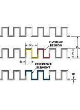 The linear wave incident upon the polarizer (Einc ) is resolved into two orthogonal components (E^ and E|| ), as shown in Figure 2 . An ideal polarizer produces perfect CP by resolving the two components such that they are equal in amplitude and have a 90°
 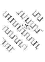 differential phase shift. An elliptically polarized wave will result if the two signals are not equal or if the phase shift (f^ - f|| ) is not 90°. The left-hand CP (LHCP) and right-hand CP (RHCP) components of the elliptical wave are given by
ELHCP = (0.5 (E^2 + E|| 2 ) - E^ E|| sin (f^ - f|| ))1/2 (1)
ERHCP = (0.5 (E^2 + E|| 2 ) + E^ E|| sin (f^ - f|| ))1/2 (2)
The axial ratio (AR) of an elliptical wave then is determined using
AR = |ELHCP + ERHCP/ELHCP-ERHCP| (3)
These parameters may be evaluated by simply substituting the orthogonal and parallel transmission coefficients calculated by the software into the equations. PMM places these transmission coefficients (amplitude and phase) into an ASCII file when the spreadsheet option is used.
Defining the Geometry and Modes
PMM models an infinite array of identical elements and requires the description 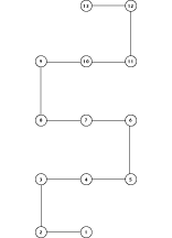 of a single finite element and spacing to adjacent elements. As shown previously, the meander-line structure can be modeled as an infinite repetition of the reference element. The Dz spacing must be set such that a perfect overlap of the reference element exists for the program to calculate an accurate analysis. This result is achieved by setting Dz to one-half the length of the reference element and defining the overlapping nodes as coincident. A detail of the reference element is shown in Figure 3 . When defining the structure, the numbers of points and segments are chosen such that no line segment exceeds 0.3 l5
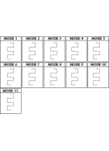 The required mode configuration to be placed on the reference element can be determined from the current density distributions predicted by Terret et al.1 Distinct differences exist in the orthogonal and parallel current distributions and two different modal layouts are expected to be required. Two modes were modeled as defined by Yoder.6 Two runs of the program are required because of the different modal definitions. In order to increase efficiency, a single definition that could be used for both polarizations was investigated. The single mode definition, shown in Figure 4 , has results similar to those of the two modes defined previously.
A PMM input file listing that details the points and segments of a single-layer meander-line polarizer is shown in Appendix A. Explanations of the statements not defined in the listing have been published previously.5 From this input file, the software calculates the transmission and reflection coefficients from which the SWR and axial ratio are determined. An ASCII file is produced that includes all of the required parameters. A supplemental program that reads this file and calculates the LHCP and RHCP components, axial ratio and SWR is shown in Appendix B. This program incorporates Equations 1, 2 and 3.
A Comparison to Measured and Published Results
 The previously analyzed model was reanalyzed using PMM. The parameters used in the model were Dx = 10.16 mm, B = 4.32 mm, LT = 0.25 mm, C = 3.3 mm and slab thickness = 0.254 mm with an er of 2.22. Figure 5 shows the calculated values of the
 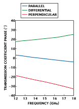 normalized susceptances and Figure 6 shows the transmission phases. As can be seen, the calculations agree quite well with the theoretical and measured predictions made previously.1
The PMM software was used in the design of a four-layer meander-line polarizer to cover the 12.4 to 18 GHz band. Each meander-line layer was etched using half-ounce copper on 0.010"-thick polytetrafluoroethelene (er = 2.2). The four layers were then assembled with a dielectric frame that held the layer-to-layer spacing to 0.190". The polarizer was mounted over the aperture of an H-plane sectoral horn and measurements were recorded.
The measured axial ratio agrees quite well with the predicted performance, as  shown in Figure 7 . The minor differences are considered to be the result of the cross-polarization parameters of the horn itself. The cross-polarization component of the horn generates the opposite sense of CP that increases the level of the axial ratio. A cross-polarization level of -31 dB produces an axial ratio of approximately 0.5 dB. The horn must be designed to have a low cross-polarization component in order to produce an optimal axial ratio response. Another parameter that affects the results is the test chamber. Low axial ratio measurements require an ideal range/chamber with a high performance (low cross polarization) source. The range used in the axial ratio measurement has a 0.5 dB uncertainty that may contribute to the overall error.
Conclusion
A meander-line polarizer converts the polarization properties of an antenna and has been used in many applications ranging from military to wireless. The polarizer may be modeled efficiently and accurately with the PMM version 4.0 computer program. The program's performance predictions have been proven to agree favorably with both measured and published data. The modeling technique has been successful in practice and has reduced the development cycle of meander-line polarizers significantly.
Acknowledgment
The author would like to thank the staff and management of Celwave RF, Marlboro, NJ, for providing a creative environment, and Harry O'Reilly and Rob Johnson for their intuitive inputs. PMM version 4.0 was used throughout the meander-line development. The software is available from Ohio State University (having been approved for general distribution by the US Air Force) for a nominal fee to cover handling and reproduction costs. Interested parties should contact the Ohio State University ElectroScience Laboratory by mail at 1320 Kinnear Rd., Columbus, OH 43212, Attention: Librarian or call (614) 292-7981, fax (614) 292-7297.
References
1. C. Terret, J.R. Levrel and K. Mahdjoubi, "Susceptance Computations of a Meander-line Polarizer Layer," IEEE Transactions on Antennas and Propagation, Vol. AP-32, September 1984, pp. 1007-1011.
2. L. Young, L.A. Robinson and C.A. Hacking, "Meander-line Polarizer," IEEE Transactions on Antennas and Propagation, Vol. AP-21, May 1973, pp. 376-378.
3. T.L. Blacknet, J.R. Burnett and S.B. Cohn, "A Design Method for Meander-line Circular Polarizers," presented at the 22nd Annual Antenna Symposium, October 1972.
4. R. Chu and K. Lee, "Analytical Model of a Multilayered Meander-line Polarizer Plate with Normal and Oblique Plane-wave Incidence," IEEE Transactions on Antennas and Propagation, Vol. AP-35, June 1987, pp. 652-661.
5. L.W. Henderson, "Introduction to PMM, Version 4.0," Technical Report 725347-1, Ohio State University ElectroScience Laboratory, Department of Electrical Engineering, prepared under contract SC-SP18-91-0001 for Mission Research Corp., Santa Barbara, CA, July 1993.
6. S.W. Yoder, "Analysis of Strip Gratings and Meander Lines Using Doubly Periodic Infinite Planar Arrays," Master of Science Thesis, Ohio State University, 1992.
7. J.S. Hollis, T.J. Lyon and L. Clayton (eds.), Microwave Antenna Measurements, Scientific-Atlanta, Atlanta, GA, 1970.
Ronald A. Marino received his BSEE from Pennsylvania State University in 1981 where he specialized in antennas and microwaves. In 1982, he joined Litton Amecom as a senior member of the technical staff where he designed antennas for electronic warfare applications and received a patent for a conformal interferometer array, which incorporated printed spiral antennas. In 1989, Marino joined MDM where he designed a modular 44 GHz slot array composed of 5184 radiators. In 1994, while with Dorne & Margolin, he received an engineering achievement award for technical excellence in proposal preparation. He has also been responsible for developing automated turnkey antenna test facilities and and analysis tools for Litton Amecom, Northrop DSD, MDM Inc., Dorne & Margolin, Datron Transco and Celwave RF. Currently, Marino works for Celwave RF as a senior antenna design engineer developing printed circuit antennas. He can be contacted via e-mail at ronaldm@uscom.com.
