An RF Distribution Amplifier
Datum
Beverly, MA
The task of delivering a centralized reference signal to a number of different equipment stations without degrading the signal or creating crosstalk can be difficult, particularly when up to 100 locations require this signal. This situation is encountered in many engineering and calibration laboratories and production test facilities.
The model FTS 6502 distribution amplifier provides a means to divide and deliver a 100 kHz to 10 MHz sine wave signal to 10 locations with high channel-to-channel isolation and low added phase noise. The unit is housed in a convenient, 1U-high, rack-mounted case, providing greater than 100 dB of isolation between outputs. Up to 10 units can be daisy-chained together providing up to 100 matched outputs, or one unit can drive another to provide almost infinite expansion capability with virtually no signal degradation.
The distribution amplifier is composed of a set of very low phase noise RF amplifiers driven from a common input amplifier. The external RF input signal is terminated in 50 W and buffered to a common bus that delivers it to the 10 output amplifiers, each with its own level detector. Each detector drives both an individual light-emitting diode (LED) and the summary fault detector, which reports any fault to the summary fault relay and LED via an OR circuit.
 The module’s AC/DC power supply converts 115 V AC to ±11.4 V DC via a full wave bridge rectifier and filter. These raw voltages then are regulated to ±6.1 V DC in four separate linear regulators. Figure 1 shows the amplifier’s RF section block diagram.
The distribution amplifier operates over the 0.1 to 10 MHz frequency range with unity gain and provides a 1 V RMS signal to a 50 W load at each output. The required input signal is 0.9 to 1.5 V RMS into 50 W and the input impedance is switchable between 50 W and high impedance. The output signals feature less than –40 dBc harmonic distortion and less than –80 dBc nonharmonic distortion. Channel-to-channel isolation is greater than 100 dB. The additive single-sideband phase noise in a 1 Hz bandwidth is better than –120 and –160 dB at 1 Hz and 10 kHz from the carrier, respectively, as shown in Figure 2 . The unit dissipates less than 10 W from either a 120 or 240 V AC supply and is capable of operating from 0° to 55°C in 0 to 95 percent noncondensing humidity.
The distribution amplifier is housed in a 10.00" x 19.00" x 1.75" case with BNC RF input and output mating connectors on the rear panel. (An alternative front mount is available.) Figure 3 shows the rear of the assembly. The entire assembly weighs less than 5 lb.
 The unit’s alarm interface consists of a set of form-C relay contacts provided on the nine-pin alarm connector on the rear apron. During normal operation, the 10 red indicator lights on the rear apron and the red indicator light on the front panel remain off, indicating the presence of an output signal. If the input signal or input buffer fails, the red indicator light on the control panel is illuminated. Likewise, if any output amplifier fails, the red control panel LED indicator light is illuminated along with the associated output connector red LED indicator. In both cases, the form-C relay changes state, indicating a fault condition. The entire assembly is reversible front to back if front-panel access to the outputs is desired.
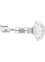
In a typical application, the FTS 6502 distribution amplifier takes the singleoutput from a cesium frequency standard and provides 10 additional buffered outputs per shelf to other equipment. This type of scenario occurs frequently in calibration laboratories, engineering facilities and production test operations. Figure 4 shows an application involving a 10 MHz input derived from a Global Positioning System (GPS) receiver delivered to multiple users requiring telemetry timing.
The FTS 6502 distribution amplifier provides a means of supplying an RF sine wave reference signal to multiple stations without degradation or interaction. The compact assembly is reliable and easy to use, and the built-in fault protection can prevent costly errors resulting from an undetected reference loss.
Datum,
Beverly, MA
(800) 544-0233 or (978) 927-8220.
