Ultra-low Noise VCOs
Z-Communications Inc.
San Diego, CA
Currently, there is a demand for lower noise performance and lower cost VCOs, especially in the upcoming personal communications service and digital radio markets. In these applications, both the Colpitts configuration, shown in Figure 1 , and the common-base configuration, shown in Figure 2 , are limited in single-sideband (SSB) phase noise performance by the resonator used. In addition, more often than not, the choice of resonator creates cost inflexibility.
 Fig. 1: The Colpitts oscillator configuration.

Fig. 2: The common-base oscillator configuration.
Current VCO Technology Limitations
Although the Colpitts configuration is suited ideally for lower frequency applications, it does not lend itself to wider band applications when higher operating frequencies are required. Furthermore, although the common-base configuration is suited for wider bandwidth and higher frequency operation, it does not optimize SSB phase noise performance nor does it lend itself to lower frequency operation. As a result, VCO manufacturers must employ expensive and, oftentimes, custom-designed inductors and/or ceramic resonators to generate the necessary tank-circuit Qs to achieve the demanding noise specifications of today's phase-locked loop (PLL) applications. Unfortunately, this solution intensifies the problem by introducing increased lead time associated with ceramic/custom materials and does not address the need to reduce cost.
To overcome these problems and address the cost, performance and availability concerns, the CLV series VCOs has been introduced. The VCOs feature a variety of performance enhancements to existing VCO technology that bring significant improvements to existing PLL circuits.
SSB Phase Noise Performance Improvements
The patent-pending approach, shown in Figure 3 , is derived from the common-base configuration, but through extensive phase noise modeling and other proprietary techniques, the configuration has been modified to achieve significant improvements in SSB phase noise performance over wide bandwidths. Other salient features to the design include dramatic improvements to harmonic attenuation over conventional VCOs and increased tolerance to load mismatching without costly isolating amplifier stages.
 Fig. 3: The CLV series oscillator configuration.
It is important to emphasize that the CLV series does not employ a high Q ceramic resonator or a high reverse isolation amplifier at the output -- both of which are found in existing VCOs and at a considerable cost to the end user. The unique approach to the CLV series, where noise optimization is key, is a revolutionary advance in VCO technology.
An Example
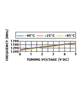
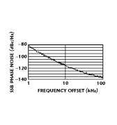
The typical tuning curve of the model CLV1320E VCO is shown in Figure 4 . Note that it is similar to other conventional, microstrip resonator-based VCOs in that it covers a moderate bandwidth of approximately 50 MHz under ambient conditions with a tuning voltage of 0.5 to 4.5 V DC (the device is powered by 5 V DC). The 1295 to 1345 MHz frequency range is generated with an average linearity of 1.1:1. However, the device's SSB phase noise plot, shown in Figure 5 , is considerably better than conventional VCOs.
 Fig. 4: The VCO's typical tuning response.

Fig. 5: The VCO's SSB phase noise at 1320 MHz.
The typical SSB phase noise performance for this device and others introduced thus far is approximately -115 dBc/Hz at 10 kHz from the carrier. With increasing bandwidth and frequency, this noise level can degrade. For example, a typical CLV VCO that generates a frequency range of 810 to 890 MHz within a 5 V DC tuning range has an SSB phase noise of approximately -112 dBc/Hz at 10 kHz offset. Other CLV VCOs introduced at 1800 MHz with a bandwidth of 100 MHz have a typical SSB phase noise of approximately -105 dBc/Hz at 10 kHz.
As mentioned previously, the CLV series VCOs do not employ ceramic resonators but the tank circuit of the oscillator reproduces the same, if not higher, Q values necessary to achieve the SSB performance demanded in today's radio applications. One benefit of the higher Q tank circuit in the CLV series VCOs is the improved pulling response. Measured data taken on the CLV1320E depict a pulling response of
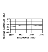
In addition, the CLV series exhibits improved harmonic attenuation over conventional VCOs on the market today. Figure 6 shows the second-harmonic performance data for the CLV1320E across the 2590 to 2690 MHz frequency band (twice the fundamental frequency of operation). The CLV series does not employ a costly filter circuit. The attenuation of the second and other harmonics is a result of the VCO's unique design. Depending on the end user's application and system requirements, this improved harmonic performance may alleviate altogether the need for additional harmonic attenuation (filter stage) at the output of the CLV VCO.
 Fig. 6: The VCO's typical second-harmonic output.
Conclusion
The latest developments in VCO SSB phase noise improvement have been described. These improvements are attributed to a patent-pending design that eliminates the need for expensive ceramic resonators and represents a low cost solution for volume production. Other benefits of the advanced VCO technology include improved harmonic attenuation and improved tolerance to load mismatching. These advances have come about due to the market need for an ultra-quiet VCO at a low cost. Detailed information regarding the CLV1320E or other CLV series VCO products can be found at the company's Web site at http://www.zcomm.com. Price: $24.95 each (CLV Series) (five pieces, minimum). Delivery: stock to three weeks.
Z-Communications Inc.,
San Diego, CA (619) 621-2700.
