In recent applications of telecommunications and remote sensing at radio, microwave and terahertz frequencies, the exploitation of ultra-wideband (UWB) antennas is growing steadily.1 In subsurface prospecting, for example, they can provide higher imaging resolution and better target characterization.2
The design and analysis of such high performance antennas exhibit significant challenges.3 In particular, in the case of GPR systems, typical requirements include not only a broad operating bandwidth for short “real” and “synthetic” pulse radiation, but also negligible interferences caused by scattering from undesired directions and small size to make the system portable.2 Furthermore, since the antennas work in close proximity or in contact with the investigated structure, their input impedance and radiated field are affected, so that the properties of the background medium must be taken into account in designing and analyzing the antenna performance.2,4 Finally, the mutual interaction between transmitting and receiving antennas must be also considered. It is very difficult to measure the antenna properties (the radiated field, for example) under operative GPR conditions, characterized by an inhomogeneous variable scenario.5 This gives rise to the need for a full-wave analysis of the antenna. An accurate modeling of the antenna is crucial for the exploitation of inverse scattering approaches to the GPR prospecting, since the accurate knowledge of the incident field (that is the field impinging on the investigated zone in absence of scattering objects) is one of the key factors ensuring the reliability of the results of inversion algorithms.6

In this article, the modeling and characterization of two bow-tie antennas, designed for GPR prospecting and working in the 600 to 1400 MHz frequency band, are described. The antennas are numerically analysed in different operative situations by the well-known software High Frequency Structure Simulator (HFSS) from Ansoft7 based on FEM,8 which permits accurate modeling of both the feed and the radiating elements of the antennas. The numerical results are then compared with measurements collected in laboratory conditions at the Dipartimento di Ingegneria dell’Informazione of the Second University of Naples, Italy.
Antenna Model and Simulation

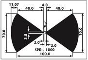
The two bow-tie antennas of interest have been designed and built at the Dipartimento di Ingegneria Elettronica, University of Florence, Italy, for GPR prospecting. The geometry of the radiating elements is shown in Figure 1, with the dimensions given in millimeters. They are made up from a 35 mm thick copper layer, deposited on a substrate of epoxy glass FR4. A microstrip Marchand balun circuit, implemented by means of three coupled lines, provides a balanced excitation of the radiating elements. The related printed circuit is fabricated using microstrip technology on epoxy glass FR4, and is connected directly to the antenna feed. The connection on the unbalanced side uses a conformable coaxial cable. The balun is centrally positioned with respect to the antenna, as shown in Figure 2. In order to achieve a negligible back radiation, the feed and radiating elements are placed into a 171.5 × 120.6 × 106.7 mm metallic box. The box is filled with five layers of dielectric absorbing material (carbon-loaded polyurethane foam) in order to reduce undesired reflections. The balun circuit is mechanically protected with a silicon varnish and by plastic material holders, fixed on two sides of the printed circuit so it does not touch the surrounding absorbing material.
The numerical analysis of the antenna has been performed for the full three-dimensional model using HFSS.7 The geometrical model is divided into a large number of tetrahedra, where each single tetrahedron is a four-sided pyramid. This collection of tetrahedra is referred to as the finite element mesh. The curved metal surfaces of the antenna are modeled by a triangular mesh, constituted by the tetrahedra faces. The radiation boundary conditions are used for the mesh termination so as to simulate a free-space problem. The code uses an iterative process, called adaptive analysis, in which the mesh is automatically refined in critical regions: first, a solution based on a coarse initial mesh is generated; then, the mesh is refined in areas of high error density, and a new solution is generated. When some selected parameters converge to within a desired limit, the code breaks out of the loop. The structure to be simulated was described previously when the model of the balun circuit and the radiating elements were depicted.

Numerical Simulation and Experimental Results
The configuration with the two antennas close to each other, in the same plane and pointing in the same direction, is considered. This “reflection” configuration represents the typical operation situation for a GPR system. The overall geometry of interest is shown in Figure 3, where the radiating elements lay in the x-y plane and are aligned along the y-axis. The UWB performance of the antenna is evaluated in terms of the scattering matrix between the input port of the transmitting antenna and the output port of the receiving antenna. The reference planes are located at the connectors on the back of the boxes enclosing the two antennas. The chosen convergence criterion of the FEM code is based on the change of the four Sij (i,j = 1, 2) elements of the scattering matrix between two consecutive iterations at finer meshes. If at the Nth iteration, ΔS is


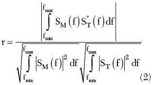
when ΔS ≤ 0.01, the analysis stops; otherwise, it continues with a refined mesh. The computer scattering parameters have been evaluated by assuming 50 Ω for the characteristic impedance of the feed-lines. The results of the numerical analysis have been compared with measurements collected at the Electromagnetic Diagnostics Laboratory of the Second University of Naples. The measurements have been collected in a semi-anechoic environment by an automatic system for the measurement of the near field at microwaves.9 As a fidelity index to qualify the agreement between simulated and measured scattering parameters, the correlation coefficient


is adopted, where SM(f) and ST(f) denote the measured and the numerically calculated scattering matrix elements, respectively, and * stands for the complex conjugate. The integrals are performed over the whole frequency band of the antenna.
The Free-space Case
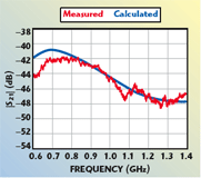
The first analysis is performed for radiation in free-space. The two antennas are spaced 15 cm away from each other. The scattering parameter S11, which accounts for the influence of the receiving antenna on the mismatching of the transmitting one, is considered. Figure 4 shows the comparison between the measured (red line) and the computed (blue line) amplitude of the scattering parameter S11, whereas the value computed for a single antenna case (green line) is displayed for comparison to better appreciate the proximity effect between the antennas. As can be seen, the agreement between measurement and computation is good and r = 0.77. Then, the scattering parameter S21, which accounts for the mutual coupling between the transmitting and receiving antenna, is considered. Figure 5 shows the comparison between the measured and computed values with r = 0.9. The analysis in free-space is completed by evaluating the near field, that is the field inside the computation domain; Figure 6 shows the amplitude of the x-component of the electric field. Finally, in Figures 7 and 8, the radiation patterns in the two x-z and y-z principal planes are shown as calculated by the HFSS software from the computed near field for two close antennas (red line) and the single antenna case (blue line), respectively. As can be appreciated, the proximity of the receiving antenna causes an asymmetrical radiation pattern in the y-z plane.

The Tuff Masonry Case
In the second analysis, the case of the two antennas placed in front of a tuff masonry is considered. The distance between the antennas and the masonry is 3.5 cm. The thickness of the masonry is 11 cm. The electromagnetic behaviour of tuff has been characterized previously10 and a relative dielectric constant equal to 4 and a conductivity equal to 0.01 S/m are assumed. Figure 9 shows the comparison between the numerically evaluated and the measured magnitude of the scattering parameter S11. The correlation index is r = 0.77. The scattering parameter S21 is also considered. In this case, a good agreement is observed between the numerically evaluated and the measured scattering parameters (see Figure 10). The correlation index is r = 0.96. Finally, Figure 11 shows the amplitude of the x-component of the electric field in the computation domain; inside the masonry, the stationary behavior of the field is observed due to standing waves propagation inside the masonry.

Conclusion
This article shows how a FEM-based numerical analysis, accounting for the full complexity of a bow-tie antenna, and the results of experimental measurements agree well to characterize UWB sensors, both in free-space and in the more challenging case of a non-homogeneous scenario. This work falls within the more general activity on sensor characterization developed at the Second University of Naples and at IREA. The final goal of this accurate modeling aims to improve the reconstruction of tomographic images in inverse scattering problems.
Acknowledgments

The authors thank M. Pieraccini and F. Parrini of the University of Florence for providing the detailed description of the antennas. This work is part of the project of the Regional Center of Competence “Analysis and Monitoring of the Environmental Risk” supported by The European Community on Provision 3.16.
References
1. A. Hoorfar and V. Jamnejad, “Electromagnetic Modeling and Analysis of Wireless Communication Antennas,” IEEE Microwave Magazine, March 2003, pp. 51–67.
2. D.J. Daniels (Ed.), Ground Penetrating Radar, Second Edition, The Institution of Electrical Engineers, London, England, 2004.

3. X. Li, S.C. Hagness, M.K. Choi and D.W. van der Weide, “Numerical and Experimental Investigation of an Ultra-wideband Ridged Pyramidal Horn Antenna with Curved Launching Plane for Pulse Radiation,” IEEE Antennas and Wireless Propagation Letters, Vol. 2, 2003, pp. 259–262.
4. K.H. Lee, C.C. Chen, F.L. Teixeira and R. Lee, “Modeling and Investigation of a Geometrically Complex UWB GPR Antenna Using FDTD,” IEEE Transactions on Antennas and Propagation, Vol. 52, No. 8, August 2004, 1983, pp. 1983–1991.
5. A.G. Yarovoy, “Comprehensive Experimental Analysis of GPR Antennas,” Proceedings of the Tenth International Conference on Ground Penetrating Radar, Delft, The Netherlands, June 2004, pp. 153–156.
6. F. Soldovieri, R. Persico and G. Leone, “Effect of Source and Receiver Radiation Characteristics in Subsurface Prospecting Within the Distorted Born Approximation,” Radio Science, Vol. 40, No. RS3006, May 2005.

7. http://www.ansoft.com/products/hf/hfss/.
8. J. Jin, The Finite Element Method in Electromagnetics, Second Edition, John Wiley & Sons Inc., New York, NY, 2002.
9. A. Brancaccio, G. Leone, R. Pierri and F. Soldovieri, “Experimental Validation of a PO-based Shape Reconstruction Algorithm,” IEEE Transactions on Geoscience and Remote Sensing, Vol. 40, No. 9, September 2002, pp. 2093–2099.
10. A. Brancaccio, F. Soldovieri, G. Leone, D. Sglavo and R. Pierri, “Microwave Characterization of Materials in Civil Engineering,” Proceedings of the European Microwave Association, June 2006.
Francesco Soldovieri received his Laurea degree in electronic engineering from the University of Salerno, Italy, in 1992, and his PhD degree in electronic engineering from the University of Naples, Italy, in 1996. In 1993, he joined the electromagnetic research group of the University of Naples and held a postdoctoral fellowship at the same university from 1998 to 1999. In 1999 to 2000, he collaborated with the research group on applied electromagnetism at the Second University of Naples. Since 2001, he has been a researcher at the Institute for the Electromagnetic Sensing of the Environment of the Italian National Research council (IREA-CNR). His research interests include electromagnetic diagnostics, inverse scattering and GPR applications.

Adriana Brancaccio received her Laurea degree summa cum laude in electrical engineering in 1991 and her PhD degree in 1994 from the University of Naples, Italy. Since 1994, she has been an associate researcher and, from 2001, a professor of electromagnetics in the department of information engineering at the Second University of Naples, where she is in charge of the applied electromagnetics laboratory. Her research interests include nonlinear inverse scattering problems, subsurface sensing and scattered field measurements.
Giovanni Leone received his degree in electronic engineering in 1981 from the University of Naples, Italy. From 1986 to 1992, he was an associate researcher in electromagnetics at the University of Salerno, Italy. Since 1992, he has been an associate professor, first at the University of Salerno and, since 1995, at the Second University of Naples. In 2000, he became a full professor at the University of Reggio Calabria, where he is responsible for the funding from the Italian Space Agency and from the National Research Council. Since 1999, he has been a member of the scientific committee of CREATE. He cooperated with SUPELEC in Paris and in research activities about inversion algorithms for subsurface radar within a program funded by the Ministry of Scientific Research. His research interests include the properties of radiated fields with application to antenna measurement techniques, inverse problems in antenna synthesis, phase retrieval of radiated fields and more recently inverse scattering for material diagnostics and buried objects sensing.
