Increasingly satellite operators are focusing on utilizing the Ka-Band to expand capacity. Although by definition the Ka-Band covers the frequency band from 26.5 to 40 GHz, Ka-Band for satellite applications generally uses the frequency range around 20 GHz for the downlink and 30 GHz for the uplink. Ever-growing SatCom bandwidth needs, overcrowding of the radio frequency spectrum and the increasing demand of satellite communications have been the main drivers for this development.
Iridium, which has announced the launch of Iridium NEXT via Ka-Band in 2015, and Eutelsat, which already operates on Ka-Band technology, are just two of many operators demanding Ka-Band frequencies. Such satellite communication systems provide broadband network access for mobile ground, maritime and airborne antenna systems. These systems – commonly called SatCom on-the-move – are being introduced on a large scale all over the world for commercial, as well as for governmental (civilian and military) use.
The increase in frequency from Ku- to Ka-Band offers broad coverage of bandwidth in this very rapidly progressing technology. The utilization of higher frequencies requires faster electronic components, which, in the past, have been particularly expensive. However, due to rapid technological progress, competitive components are currently available. With an increase of Ka-Band applications and the associated optimizations of single components that comprise it, the belief is that prices will get closer to the price level of Ku-Band.
A moving satellite terminal requires a highly sophisticated beam steering system in order to continuously track the satellite during operation. There are two basic technologies that can be employed for pointing an antenna beam: The electronically phased-array antenna and the mechanically steered pencil beam antenna.
Space Restrictions
When the latter system is used, the strong space restrictions imposed by a mobile SatCom terminal require the adoption of a small aperture antenna together with a low-profile pedestal. Likewise, the rotary joints employed for signal transmission along the mechanical steering axes need to be small and are often shaped specifically for the application. At the same time, bi-directional high data rate communications over Ka-Band SatCom require a bandwidth spread of more than 1 GHz on the uplink and downlink for both commercial and military systems.
In order to provide equipment manufacturers with rotary joints tailored to the specific requirements of SatCom systems, SPINNER has developed the new BN 153130 dual-channel rotary joint for Ka-Band applications. Excellent electrical and mechanical performance and a long lifetime define this solution as a reference standard in electrical and mechanical performance.
The product line follows a common design philosophy that is characterized by excellent electrical and mechanical performance, allied to a highly reliable design. In principle, RF rotary joints can be classified into two categories:
- Contacting rotary joints, where the inner and outer conductor of the fixed and rotating part are connected via galvanic contacts.
- Non-contacting rotary joints, where the RF signals are transmitted via axial and radial chokes (capacitive coupling).

Figure 1 Outline drawing of the BN 153130 Ka-Band rotary joint [dimensions in mm (in)].
Non-contacting Design
The BN 153130 dual-band rotary joint is realized as a non-contacting design. The main advantages with this design are that as there is no contact then there is no abrasion, and it has small dimensions (39.1 mm maximum length and 63.5 mm flange diameter), while accommodating high frequencies. Besides good RF performance, the Ka-Band rotary joint is characterized by a lifetime of more than 20 million revolutions. Figure 1 shows BN 153130's design.

Figure 2 L-shaped dual-channel Ka-Band rotary joint.
The ability to produce a rotary joint of such small dimensions is very significant. For many mobile satellite communication systems being developed, there is a requirement to significantly reduce the height of the radomes under which the SatCom system is installed. The reason is the need to improve the drag coefficient, which implies that less installation space is available for the antenna, as well as for the whole pedestal. Thus, there is increasing demand for low profile rotary joints to be used in SatCom radomes. SPINNER has taken up the challenge and developed a Ka-Band rotary joint with reduced height, which means that the overall system can be built lower. This can help save fuel (on an aircraft, for example).
CHARACTERISTICS
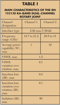
Figure 2 shows the L-shaped dual-channel BN 153130 Ka-Band rotary joint; the main characteristics of this rotary joint are summarized in Table 1. As the table illustrates, to be able to achieve superior system performance, it is necessary to achieve very low insertion loss, VSWR and high isolation values. These superior electrical properties are the result of many years of design experience, careful development, the use of top quality materials and high precision manufacturing.

Significantly, the BN 153130 dual- channel rotary joint also covers the preferential military frequency range for downlink frequencies (19.7 to 21.2 GHz) and uplink frequencies (29.5 to 31 GHz), which military customers are demanding. In addition, a broadband version for civil applications is also available with 17.7 to 21.2 GHz for the downlink and 27.5 to 31 GHz for the uplink. The ability to cover both military and civil requirements is an attractive solution for customers.
Summary
The new BN 153130 dual-channel Ka-Band rotary joint completes the SPINNER product portfolio at the upper frequency range. The result of this work is a non-contacting dual-channel Ka-Band rotary joint that guarantees outstanding electrical properties even under severe conditions (-40° to 70°C) over a long service life and offers an excellent price-performance relationship.
SPINNER GmbH
Munich, Germany
+49 89 12601 1160
e-mail: info@spinner-group.com
www.spinner-group.com
