

In this part, we will review the performance of a VRM output with a changing input voltage, in this simple mathematical expression:
ΔVOUT / ΔVIN
The goal of this part is to link this "ΔVOUT / ΔVIN" performance in multiple measurement domains: dc, time-dynamic/transient, frequency domain.
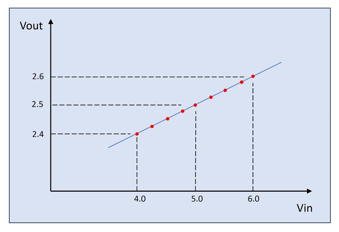
In dc characteristics, this performance is called "line regulation". We can find line regulation curves in most VRM datasheets, as in the example in Figure 1.

Behind the scenes, the curve plotted in Figure 1 must consist of multiple actual measured data points - the red dots in the raw plot in Figure 2.
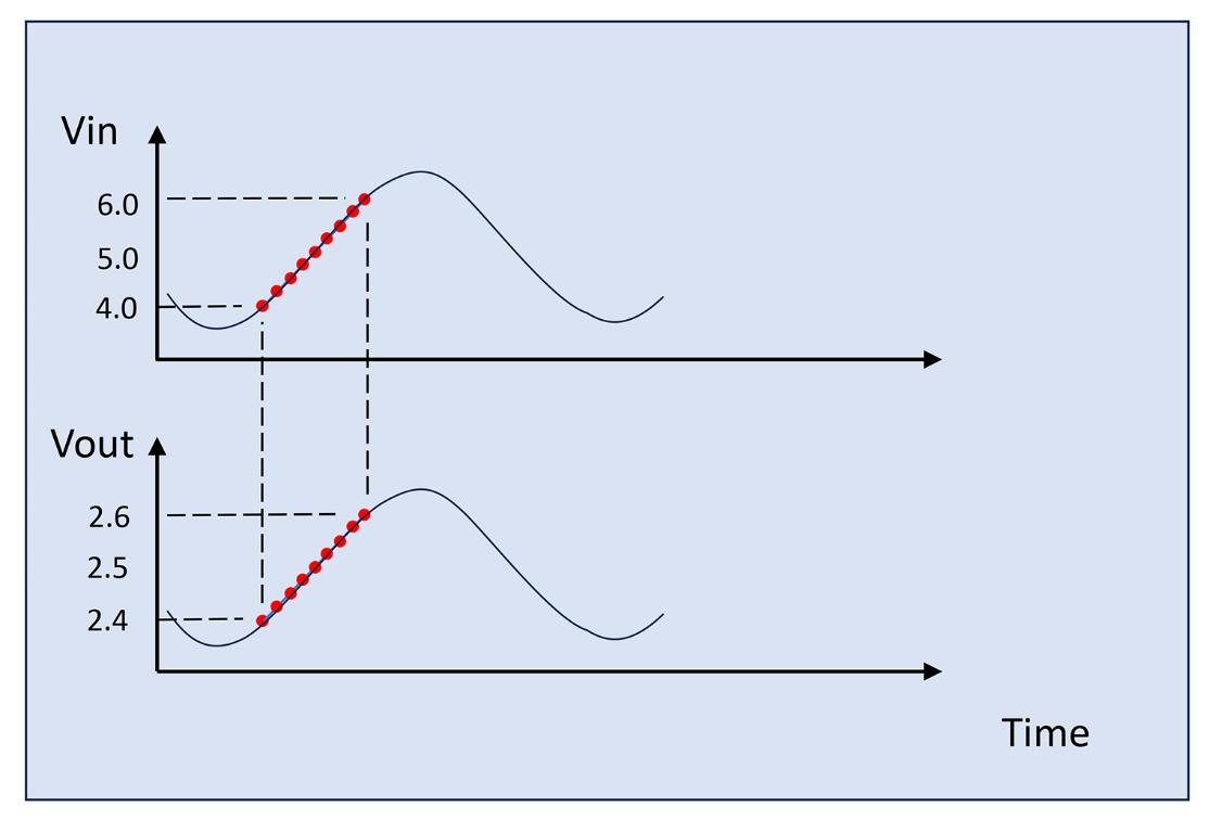
When we think of the actual bench test an engineer used to take these data points, the engineer probably swept VIN by turning the knob of a bench-top dc supply unit. By plotting this operation in time, we get the data points as in Figure 3. For the following discussion, let’s assume it took 10 seconds per data point.

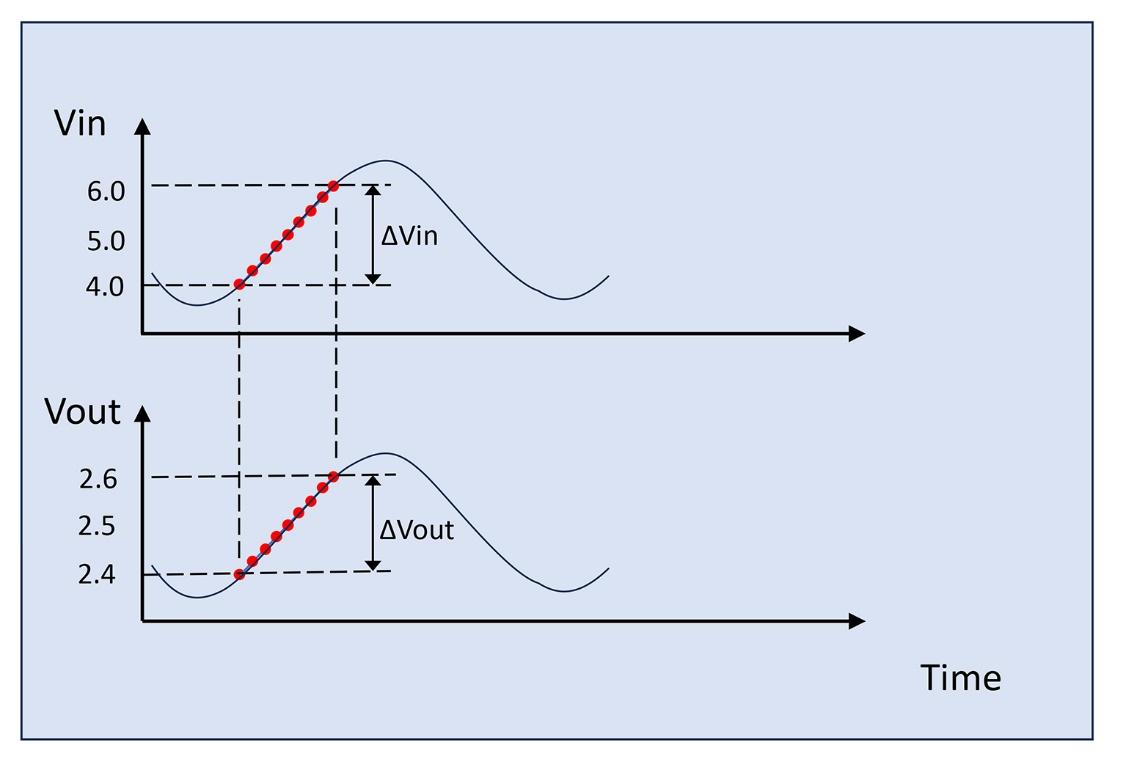
Now, we can approximate the above time related data-taking as part of longer sinusoidal VIN sweep through only half of a sine period (bottom peak to top peak) as in Figure 4.
The portion actually measured consists of 9 data points from peak-to-peak. Per our assumption of 10 s per point, this is 90 seconds for the half cycle, or a total of about 180 seconds for the full sinusoid. So, the engineer took this line regulation curve effectively running a 5.6 milli-Hz VIN sweep in the frequency domain.
When this engineer decides to program their measurement process in an automated characterization system, this VIN sweep can be faster and it could be 100ms per data point. Then, the sweeping frequency becomes 0.56Hz. When we use an IC tester machine to check this line regulation in device production, this sweeping frequency goes much higher, near the 100Hz range.
Now we can plot the same "ΔVOUT / ΔVIN" parameter with different frequency sweeping rates and produce a PSRR curve in the frequency domain.
Figure 5 and 6 are the definition of "dc line regulation" and "one frequency sweep rate of PSRR". Based on the above step-by-step illustrations, we know that these two represent the same VRM performance from different viewpoints.

Simulation: Connecting "Line Regulation" and PSRR
An example simulation Figure 7, illustrates how "line regulation" and PSRR are connected.
This simulation deck can be downloaded from the Qorvo repository at GitHub.
We use the same baseline p-FET LDO model from a previous part of this series, but this time, we modify the schematic by adding an equivalent series inductance (ESL) to its output capacitor block, moving the AC source from the reference to its power input "VIN" and adding an RC low-pass filter for the reason we will review below.
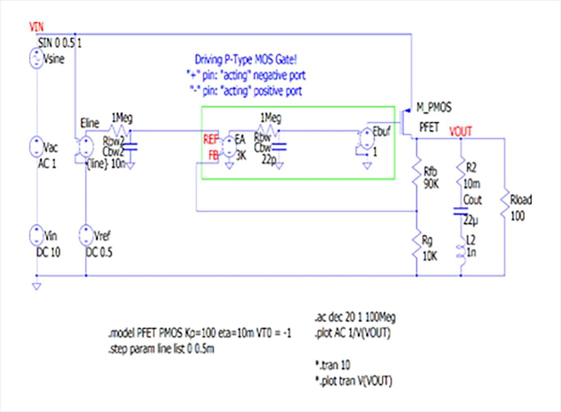
The circuit element "Eline" is a voltage controlled voltage source and it intentionally injects power line ripple "VIN" into the reference voltage via the 16Hz cut-off RC filter formed by "Rbw2" and "Cbw2". In this AC simulation, we change the gain of the "Eline" element so to switch on and off the impact of this intentional input voltage ripple coupling to the reference.
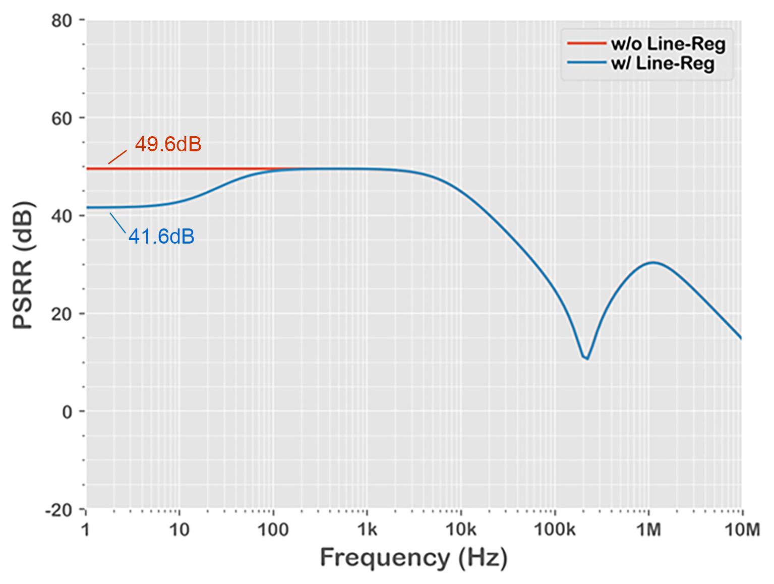
As observed in the resulting plot in Figure 8, the intentional input voltage ripple coupling (blue line) degrades from the no coupling (red line) performance.
By running a transient simulation of the same model by switching the simulation text in the schematic from ".ac" to ".tran" (or using a Python script in the download folder), we get the time domain result of Figure 9.

Note that in the PSRR plot of Figure 8, the "blue" waveform represents the actual PSRR curves of high PSRR LDOs very well within these 4 regions:
- 1Hz to 100Hz: DC performance of the regulator where DC operating points move as the input voltage changes
- 100Hz to 10kHz: High PSRR performance region of the regulator
- 10kHz to 200kHz: PSRR decay region as its negative feedback control loop loses its gain
- 200kHz and above: Performance of the output capacitor
Looking at this time domain waveform, we have 8.32mV peak-to-peak output ripple from the 1V peak-to-peak sine input with a very slow 1Hz sweep with intentional coupling.
This calculates as 41.6dB of PSRR which is exactly matches the PSRR plot Figure 8.
20 × log10(8.32mV / 1V) = -41.6dB
The lower waveform without line regulation, showing 20 × log10(3.33mV / 1V) = -49.6dB also exactly matches the PSRR plot.
Side Note: PSRR performance drop at low frequency
When I was a linear regulator product designer, we developed a very high PSRR performance device. It worked great but we found that its PSRR performance mysteriously degraded below the 500Hz range.
We wondered why and the IC design team brought up various hypotheses, including the possibility that this was a result of slow propagation of heat on the silicon die. We couldn’t conclude why we had this performance degradation below 500 Hz.
As time has passed, I now have a clear answer for this. I do remember this linear regulator device had a not-so-great line regulation at dc, because of the fairly complex circuitry to make great PSRR performance in the higher frequency region. It was a trade-off between good 10 kHz - 100 kHz PSRR and good dc line regulation.
We will review this point in next example.